Disk Imager
Overview
The advanced Disk Imager integrated into UFS Explorer makes it possible to create a full bit-by-bit clone of a source digital medium, save the content and structure of an entire storage device to a file or specify certain areas on it for copying. This component also provides an extended set of parameters aimed at maximally efficient data reading and control over I/0 errors.
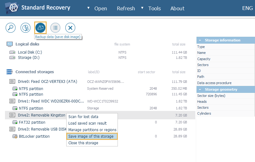
There are several ways to launch Disk imager for the chosen storage or partition: you can select it in the storages navigation pane and get the "Backup data" tool from the main toolbar or use the "Save image of this storage" option in its context menu.
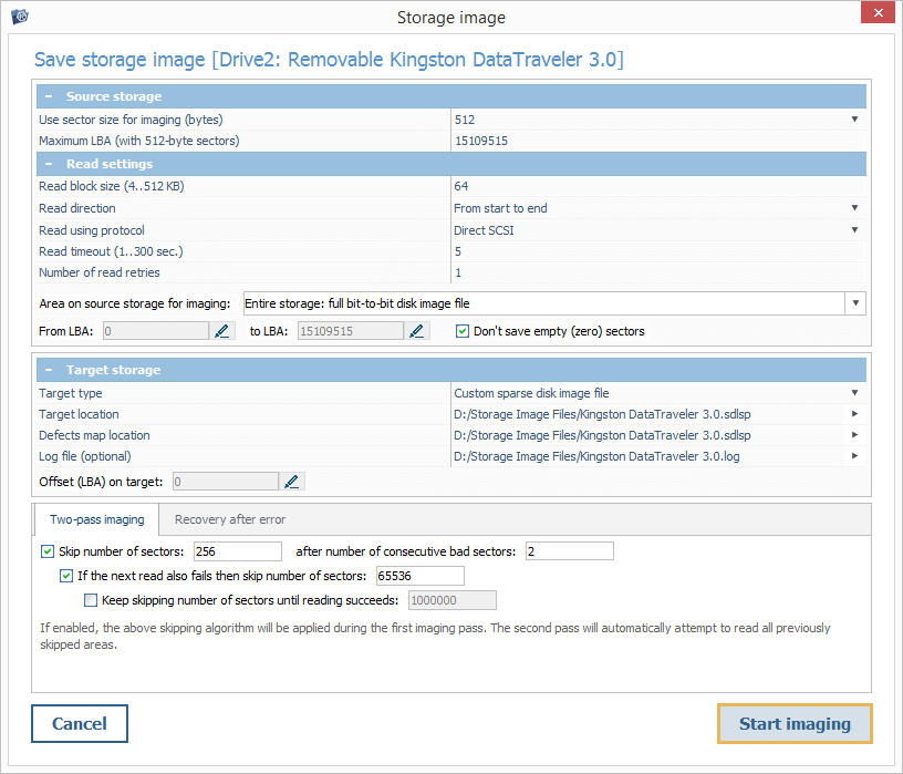
In the opened dialog, you can see the name of the source storage device for imaging at the top, the main parameters area positioned at the center and the errors handling pane located under it. The button for initiating the imaging procedure can be found at the bottom of the window.
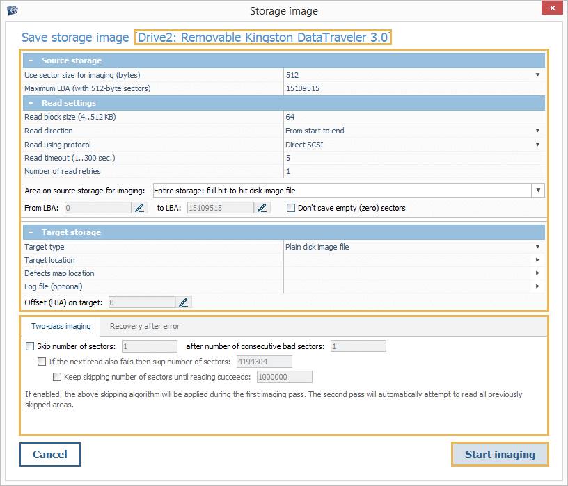
Main parameters area
This area incorporates settings that allow adjusting the procedure in accordance with the imaging strategy preferred within the given circumstances. By choosing optimal parameters, it is possible to reduce the likelihood for the physical failure caused by intensive reading from an unstable storage device and extract a maximum amount of valuable data. The pane itself consists of four separate sections:
-
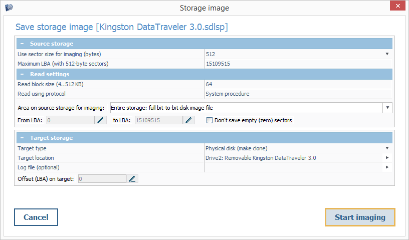
The "Source storage" section includes parameters related to the processed storage device:
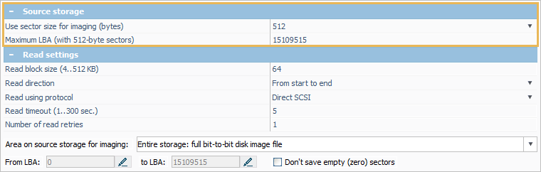
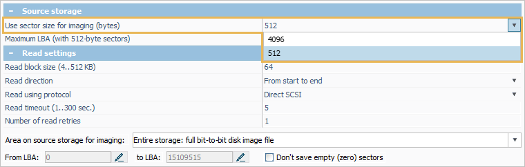
"Use sector size for imaging" – the size of the smallest addressable block on the imaged drive. The drop-down menu invoked with the "Change value" button offers the values of 4096 or 512 bytes for most drives. Yet, the parameter cannot be changed for drives that report the physical sector size as 4096 bytes via their identification data. Drives with non-standard sizes of a sector do not provide any options as well – the image of such a drive will be created with a rounded block size (for instance, 512 bytes for a 520-byte sector drive).
"Maximum LBA" – the total number of sectors on the drive in relation to the selected (identified) block size.
-
The "Read settings" section makes it possible to control the way the data is read from the source device:
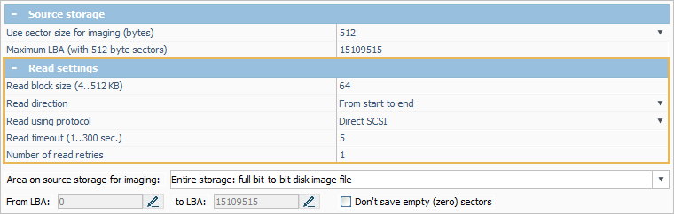
Read buffer size – the size of a data block requested per a single reading operation, ranging from 64 to 128 KB. In general, a larger size results in a faster imaging speed. However, the choice of a block size that is too large may lead to "catching" defects. Also, a very large size may not be supported by some connectors for an ATA/SCSI direct reading procedure.
Read direction – the direction in which the reading of the source device is performed. "From start to end" is the default option enabling a maximum speed. "From end to start" makes the software read the data forwards, but in blocks of several megabytes, starting from the end of the drive. The latter option may be applied to prevent rotational damage when a defective area is located closer to the start of the drive.
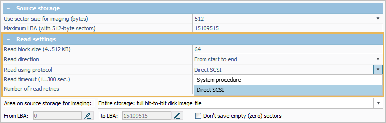
Read using protocol – the procedure employed for access to the source storage. When the "System procedure" option is selected, the reading is performed using the standard means of the operating system. This approach features wide compatibility, but, at the same time, has very a low tolerance for read instabilities. The lack of control over reading errors may result in further degradation of the failing storage device due to "hanging" caused by defective blocks or a series of defects. The "Direct SCSI" option allows using the SCSI driver for lower-level reading and bypassing certain I/O operations of the OS. In this mode, it is possible to control the procedure with the diagnostics of read errors (if supported by the adapter). The option is not available in the macOS version of the software and for PATA/SATA drives with a direct connection. The "Direct ATA" option enables the use of the ATA driver for reading Windows-based PATA/SATA drives with advanced diagnostics.
Read timeout – the time in seconds (1-300) during which a response from the drive is expected before canceling the attempt to read the sector. A short timeout speeds up the imaging process but may result in the omission of poorly readable sectors. A long timeout may provoke the rotational scoring of defects on failing drives.
Number of read retries – the number of additional read attempts that are performed for a data block that causes a read error until it will be considered to be defective. When set to "0", only a single attempt will be made to read the block. The value of 1-2 can lead to skipping of intact yet poorly readable sectors, whereas large values can cause the rotational scoring of defects on failing drives.
-
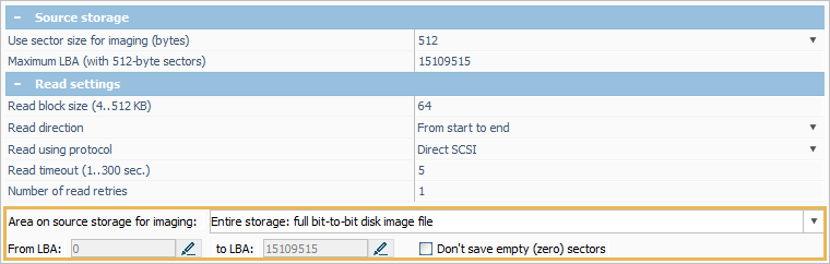
The "Area on source storage for imaging" section contains parameters as to which portion of the source storage will be imaged:
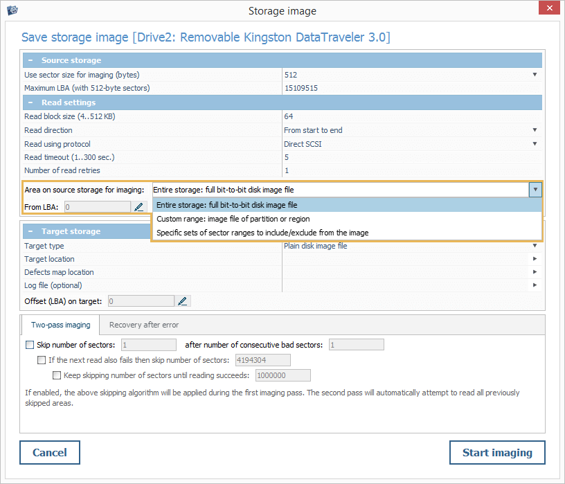
"Entire storage: full bit-to-bit disk image file" – saving everything that is possible from the first to the last block of the physical storage.
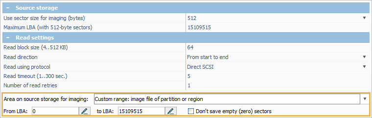
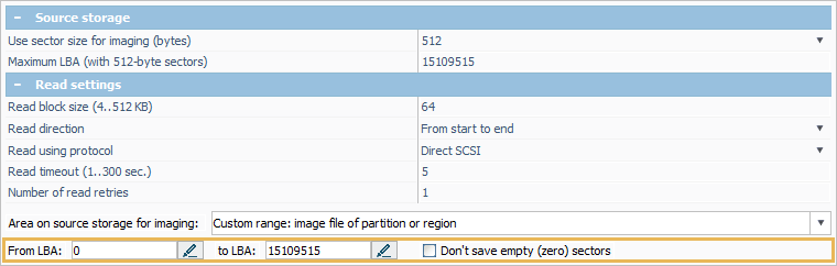
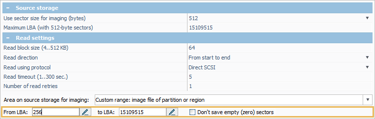
"Custom range: image file of partition or region" – saving a partial image of the physical storage. In this case, a range of blocks for imaging can be defined automatically by the program (for instance, when you launch Disk Imager for a partition) or specified manually by entering the values for the start ("From LBA") and the end sectors (To LBA).
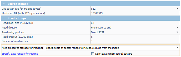
"Specific sets of sector ranges to include/exclude from the image" – creating a custom image of the storage by specifying a set of ranges that will be saved or skipped via the "Specify data ranges for imaging" function.
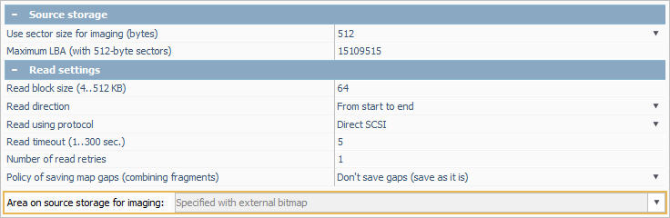
"Specified with external bitmap" – creating an image on the basis of a block map with an instruction for each block. This option cannot be chosen manually – it is activated automatically after a supported block map is applied for imaging.
"Don’t save empty (zero) sectors" – skipping sectors that contain no data.
-
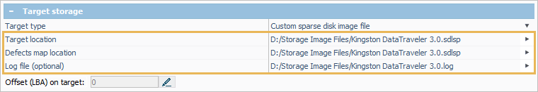
The "Target storage" section includes parameters related to the resulting disk image and its accompanying files:
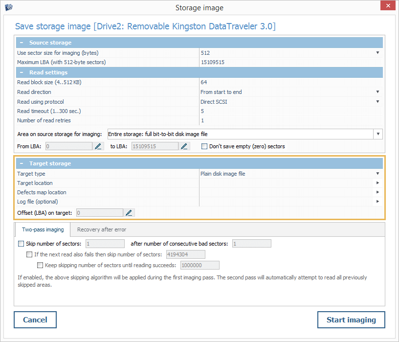
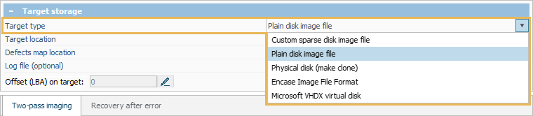
"Target type" – the type of disk image to be created. The "Plain disk image file" option can be used for saving a simple *.dsk image file, without metadata with a size that corresponds to the size of the area from which the image is created. The "Physical disk (make clone)" option allows creating a sector-by-sector copy of the source device to another storage that must be no smaller than the imaged area. The "EnCase Image File Format" option makes it possible to save an image in the *.E01 format supported by the EnCase forensic software. The "Microsoft VHDX virtual disk" option can be selected to create a virtual hard drive for its further mounting in the Windows operating system (Windows Server 2012/Windows 8 and later). The "Custom sparse disk image file" option allows performing on-demand imaging of a certain portion of data, especially when it is scattered across the storage (for example, an image of the file system metadata).
"Target location" – a target device for the cloning operation or a location on the target storage to which the disk image file will be saved. This parameter is mandatory and has to be configured for the start of the imaging process. The "Change value" button next to it opens a dialog for the target drive/folder selection. Depending on the chosen "Target type", the dialog may include the following options:
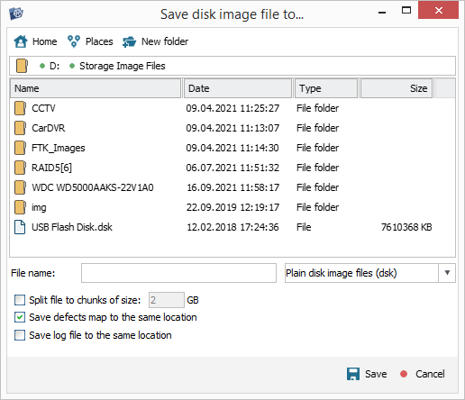
"File name" – the name of the created disk image file.
"Split file to chunks of size … GB" – writing an image to multiple files of the specified size. This option can be used when a file cannot fit onto a single digital medium (supported for plain disk images and EnCase image files).
"Save defects map to the same location" – saving the information about defects along with the disk image file (supported for plain disk images, EnCase image files and VHDX virtual drives).
"Save log file to the same location" – saving the information about events during the imaging procedure along with the disk image file (supported for plain disk images, custom sparse disk images, EnCase image files and VHDX virtual drives).
"Defects map location" – the path for a file to which the defective blocks are mapped out in the process of imaging. In addition to the header, the file contains a simple map. Each byte in it sets the status of 4 blocks (512 Bytes or 4 KB, depending on the sector size used for imaging).
"Log file (optional)" – the location for an optional log file for recording such events as reading errors, jumps, etc. that can be utilized for diagnostics.
"Offset (LBA) on target" – an offset on the target storage in the range from zero to the difference of the storage sizes, provided that the target storage is larger than the source one. This parameter can be employed to overwrite a certain part of the target storage, for instance, a single partition.
Errors handling pane
This pane contains settings related to the processing of reading errors presented in two tabs:
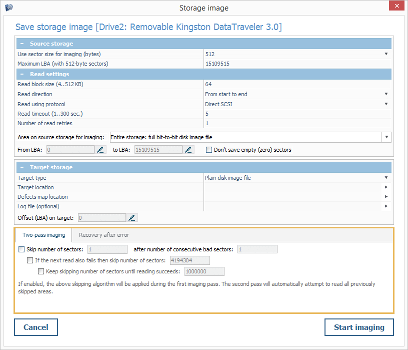
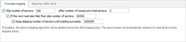
The "Two-pass imaging" tab allows configuring the algorithm used by the software for the omission of bad blocks. The defined rules for "jumps" will be applied during the first imaging pass. During the second pass, the program will try to re-read the areas skipped during the first one.
The "Skip number of sectors … after number of consecutive bad sectors …" parameter defines the size of the area that will be skipped after a number of blocks whose reading failed during the first pass. When enabled, the software counts the number of successive bad sectors. If the number is larger than or equals to the specified value, a "jump" is performed over the chosen number of sectors, and reading continues from that location. If the new readout is successful, the count is reset, and the normal mode is resumed.
The "If the next read also fails, then skip number of sectors" parameter allows performing another jump over the specified number of blocks, when the readout from the new location fails. If it is not activated, the size of the jump will be the same as that of the first one.
The "Keep skipping number of sectors until reading succeeds" parameter makes it possible to define the size of the third jump, if the reading is still not normal after the second one. If the parameter is not enabled, the size will be the same as the second jump. Such jumps will be performed until normal reading continues.
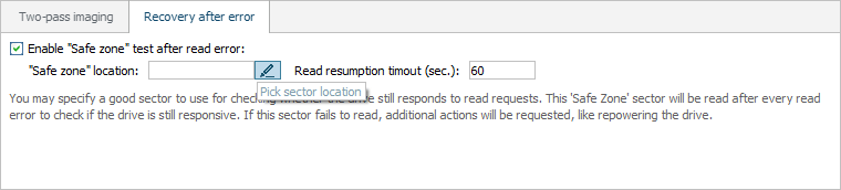
The "Recovery after error" tab can be used to set up a check whether the storage device is still able to respond to commands after a read error is encountered:
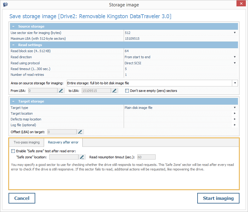
"Enable safe zone test after read error" – performing test read requests to the specified sector in order to verify that the drive is readable. If this sector cannot be read out, the software may request disconnecting and then re-connect the device.
"Safe zone location" – a sector on the source storage device that is guaranteed to be intact. This location will be referred to each time a defect is spotted, so the choice of a damaged one will interfere with the imaging process and may lead to the rotational scoring of defects.
Creating a disk image of a drive/partition
To create an image of a drive or partition, find it in the storages navigation pane and get the "Backup data (save disk image)" tool from the toolbar or select the "Save image of this storage" option in its context menu.
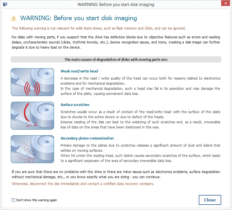
Read the warning note carefully and hit the "Close" button to proceed.
Specify the "Use sector size for imaging" parameter, if it is available for your drive. As the physical format of most modern drives is 4K, this value is enabled by default.
If necessary, modify the settings for data reading. Yet, the correction of these parameters should be performed after thorough assessment of the state of the drive and the allocation of defects.
After that, decide on the part of the source storage you want to be present in the image:
"Entire storage: full bit-to-bit disk image file" is the default option when an image of the entire drive is created.
"Custom range: image file of partition or region" is set up automatically when imaging is initiated for a partition.
If required, modify the area for imaging by specifying the first and the last sector in the range.
Alternatively, define a number of ranges to be included in or excluded from the image by providing the location of the first sector in the range and its size in sectors. This option may be useful for a repeated readout of several known ranges, or when a certain partition doesn’t have to be present in the image.
Choose the required type of image to be created:
"Plain disk image file" is the option enabled by default. In this case, the information about reading errors will be written to a mandatory defect map file within the disk image file.
If you need to clone the data within the source drive to another storage, select the "Physical disk (make clone)" from the drop-down menu. The information about defective areas will be stored in a separate defects map file.
When just a small portion of the data from the source drive is required, you may perform its imaging "by request". For this, choose the "Custom sparse disk image file" option from the drop-down menu. The state of reading will be a part of a sparse file, so a separate map is not needed.
Having set up the type of image, provide the path to its location, along with the paths for a defects map and a log, by pressing the "Change value" button next to the respective parameter.
If you are working with a failing drive, you may adjust the way in which read errors will be managed by UFS Explorer during the two-pass imaging. Depending on the condition of the device, you may set up jumps of different levels that will be performed by the imager until its normal reading resumes.
It is also possible to define the location of a "Safe zone" for test reads carried out after a failed attempt to read any other sector. Such a test on an area that is certainly readable allows distinguishing between a regular reading error and "hanging" of a device or bridge. However, if you are not totally sure about the location of an intact area of your drive, it is not recommended to enable this function.
Having made the necessary modifications, you can press the "Start imaging" button.
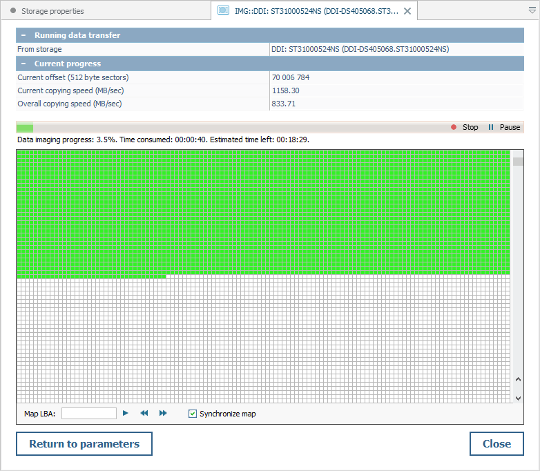
Control over the imaging process
After the process of imaging has been launched, Disk Imager makes it possible to monitor it by providing a set of advanced indicators.
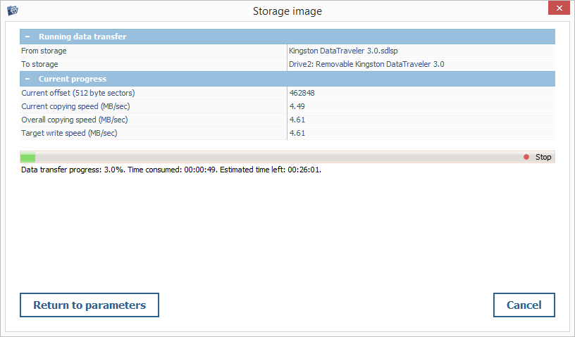
The "Running data transfer" section presents the information about the source and the target locations for imaging:
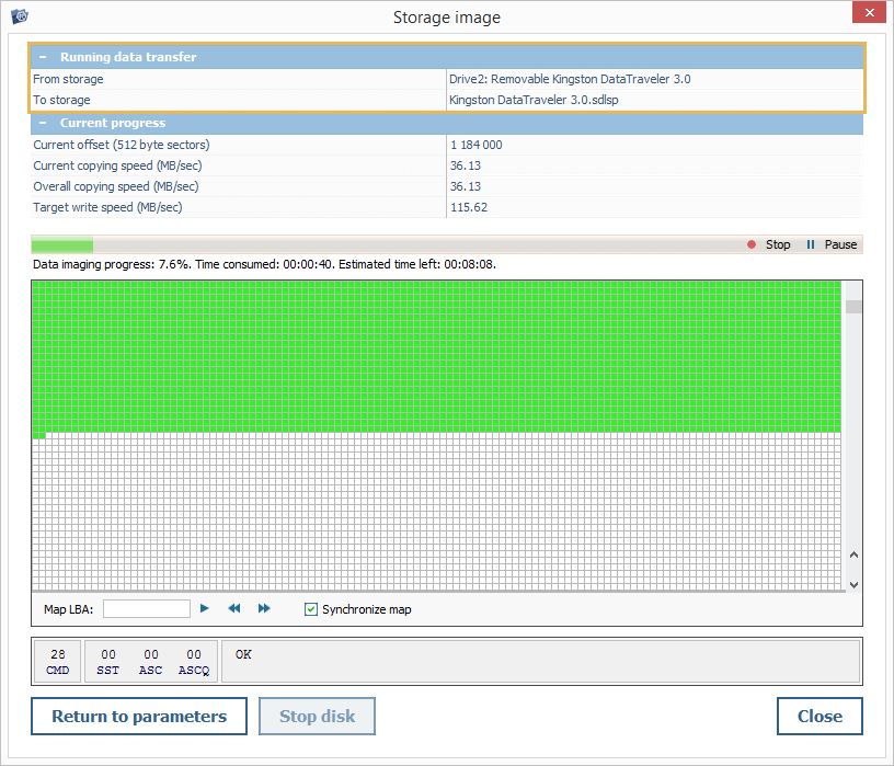
"From storage" – the name of the storage device being imaged.
"To storage" – the path on the target storage device to which the copying is performed.
The "Current progress" section allows tracking the imaging performance:
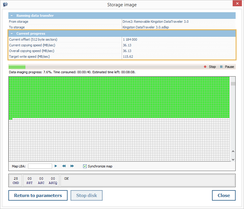
Current offset – the address of the currently imaged block.
Current copying speed – the speed at which the copying process is currently running.
Overall copying speed – the average copying speed of the currently imaged storage device.
Target write speed – the write speed of the target storage device.
The progress bar located below illustrates the progression of the ongoing imaging session. It is also accompanied by the following indicators:
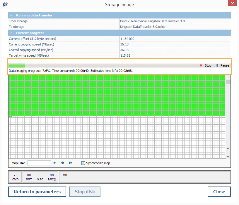
Data imaging progress – the percentage of the imaging task that is complete.
Time consumed – the amount of time elapsed from the start of the imaging session.
Estimated time left – estimated time required to complete the ongoing imaging task.
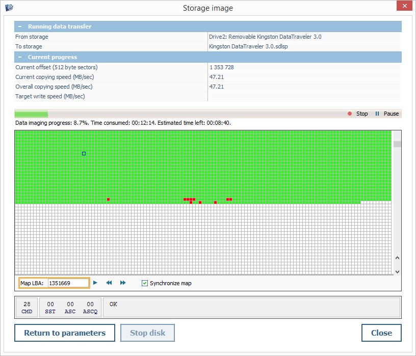
The imaging bitmap filled up in the process makes it possible to see in detail how reading is performed:
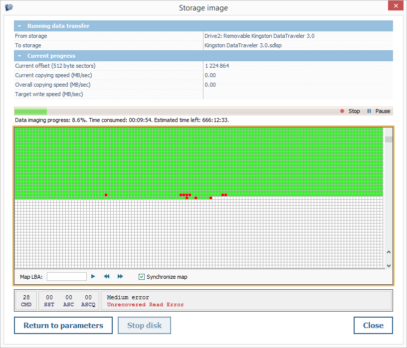
The successfully read and written blocks are displayed as green;
The blocks that contain bad sectors are marked as red;
The skipped blocks or ones that haven’t been read out yet are mapped as white.
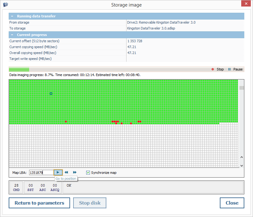
You can use the cursor to select a block within a bitmap, and its address will be displayed in the "Map LBA" field.
You can also enter the needed value in this field and press the "Go to position" button to instantly navigate to the required block within the bitmap.
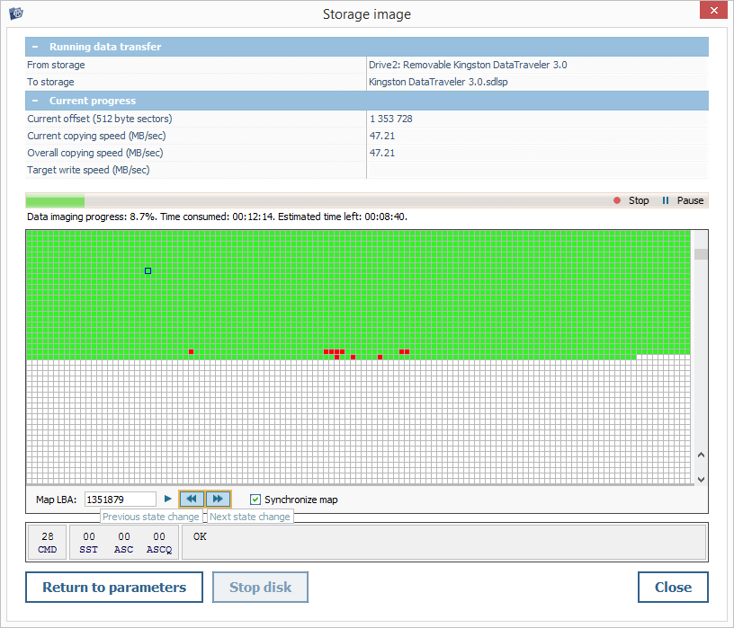
The arrow-like buttons are available for moving to the block on which the reading status has changed: for instance, you can immediately switch from an intact range of blocks to a defective one.
When the imaging procedure is running in the "Direct ATA" or "Direct SCSI" mode, the status of the device and the reading errors are also presented in the diagnostics pane. The set of indicators displayed in this pane is determined by the employed protocol:

For PATA/SATA drives imaged in the "Direct ATA" mode:
- BSY - Busy
- RDY - Device Ready
- DEF - Device Fault
- SRV - Service
- DRQ - Data Request
- ERR - Error
- BBK - Bad Block Detected
- UNC – Uncorrectable Data Error
- ANF - Address Mark Not Found
- ABR - Aborted Command
- AMN - Data Address Mark Not Found
- TZN – Track Not Found
For SAS drives imaged in the "Direct SCSI" mode:

- SST – Sense Key
- ASC - Additional Sense Code
- ASCQ - Additional Sense Code Qualifier
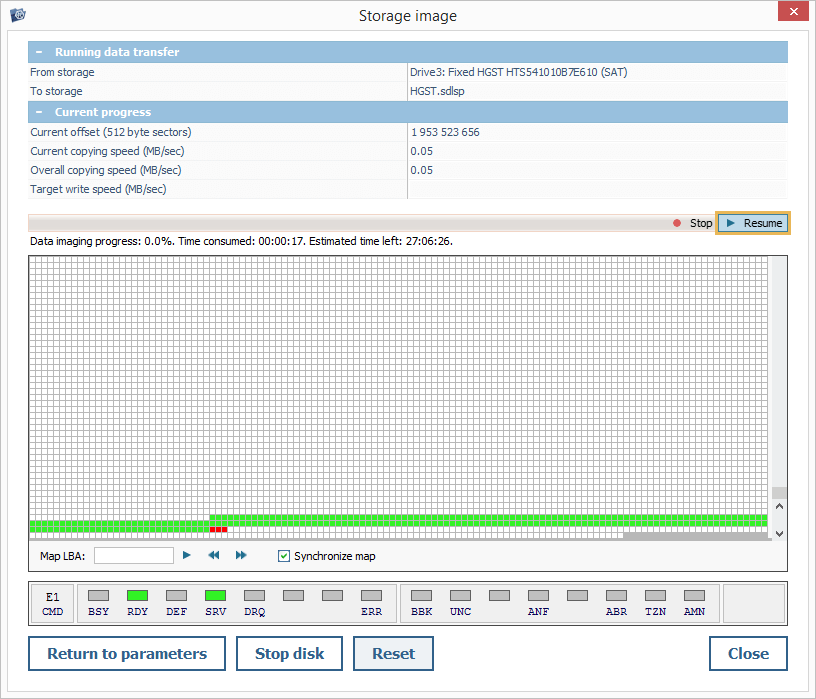
When certain issues are encountered, you can pause the procedure using the "Pause" button, put the drive in a "standby" mode with the "Stop disk" option and click "Return to parameters" to make the required adjustments.
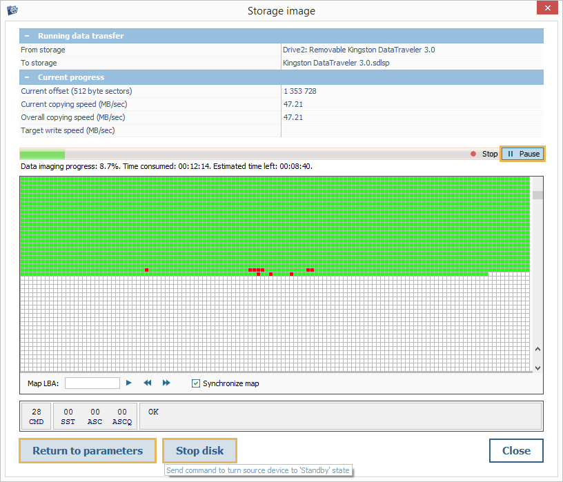
You may also try using the "Reset" button to restart the rotation of a SATA drive without power control, with parking of the read head. However, this function may not be supported for certain configurations.
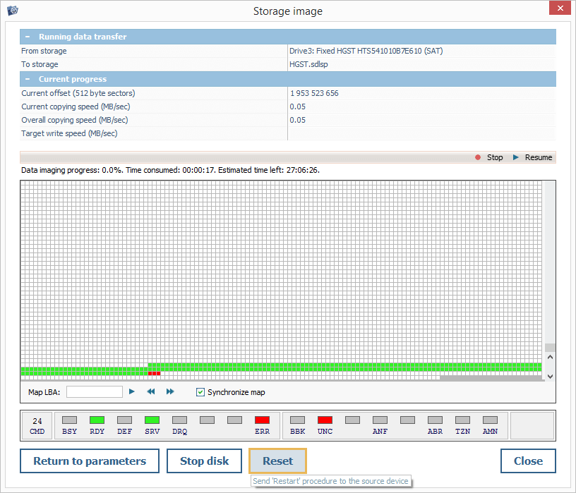
Thereafter, the procedure can be continued by pressing the "Resume" button.
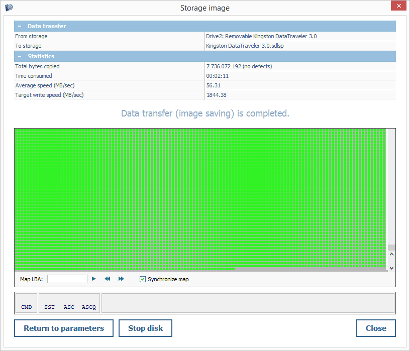
On completion of the imaging task, the progress bar will disappear, and you will see the message "Data transfer (image saving) is completed".
Creating a disk image in a simplified mode
Disk Imager is launched in a simplified mode when the source selected for imaging is another disk image, a complex storage or a file of special format. This mode can be employed to create a sub-image of an existing disk image, convert its format or save the data from the disk image to a physical disk.
In this mode, all parameters described in the Overview section are presented, except ones related to the processing of defects.
Creating a disk image from a special source
When Disk Imager is run for a supported special device, for example, for DeepSpar DDI to which the source drive is attached, it opens in a special mode instead of the standard procedure for creating disk images. This mode allows managing the imaging process on an "external" module and includes a separate configuration pane.
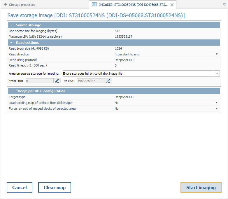
The "DeepSpar DDI" configuration pane consists of the following parameters:
Target type – the type of the special device that performs the imaging.
Load existing map of defects from disk imager – enabling the reference to the DDI bitmap for the identification of defective areas.
Force re-read of imaged blocks of selected area – enabling a repeated reading of the blocks within the area that has already been read out and written to the image.
After the procedure is initiated, the imaging performed by an external tool, while the process and its progress will be displayed in UFS Explorer.