Identification of a hard drive’s interface type and means for its connection to a computer
An internal hard disk drive is one of the most vital components of a computer’s hardware. But, unfortunately, it cannot be entirely protected from logical failures and human errors. Such issues may bring on the loss of personal user data, applications or even the essential files of the operating system. When the OS partition is affected and under some other circumstances, safe data recovery from this digital medium can be achieved only when it is attached to another operable computer. The information provided herein will aid you in determining the type of interface employed by your internal hard drive and choosing the proper method for its connection to another machine. The same recommendations will also be relevant in the context of data recovery from NAS, DAS or SAN.
Identifying the interface type of an internal hard drive
The interface of an internal hard disk drive defines the way it connects to the rest of the host system, usually the computer's motherboard, and interacts with it. Over the years, the technology used for communication has seen significant developments. First of all, the need for faster data transfers has stimulated the adoption of new techniques that could help overcome the speed bottlenecks. On the other hand, the emergence of lighter and thinner computer designs gave rise to innovations focused on a more compact physical layout. This has created distinctions between connectors available on drives that belong to different time periods. In view of the foregoing, we can broadly divide the interfaces into modern and outdated types. Modern interfaces can vary as well, depending on the environment and devices they are intended for. There are also special interface instances peculiar to a certain hardware manufacturer.
Warning: The recommendations presented in this article assume that you have adequate skills in handling hardware. Improper actions may result in physical damage to the drive and permanent data loss.
To identify the actual interface type, you should first disassemble the machine and access the hard drive. After that, examine its holder: if there is an enclosure, remove it and then check the back panel. Compare it with the following descriptions of different hard drive interfaces to find the matching one. In addition, pay attention to the form factor: most drives can measure 2.5 or 3.5 inches, while SSDs may also have other card-like dimensions.
Modern interfaces
The following interfaces can be found on hard disk drives of today's personal desktop and laptop computers, DAS and NAS appliances, as well as other mainstream products. Some of them are employed solely in advanced enterprise-level servers, workstations and storage arrays. Internal SSDs can have the same connector types as their mechanical counterparts, yet, the latest ones come with newer connection standards that allow taking greater advantage of the flash memory.
SATA (Serial ATA)
SATA hard drives and SSDs currently dominate the consumer market and are also applied in many low-end and mid-range servers. Released in 2003, SATA has replaced the older IDE interface thanks to its higher transmission rates, thinner cables and lower power consumption. Unlike IDE, SATA implements a serial connection mode and allows one drive per connector. Another important feature of SATA is that such drives can be swapped on the fly, without having to shut down the system.
SATA has two principle cable connector types: data and power. A SATA data connector has 7 horizontal pins and connects the drive one-way to a SATA socket (port) on the motherboard via a flat data cable. The end attached to the storage device may be angled for improved ergonomics. There are also compact SATA data cables specially designed for laptop assemblies.
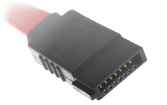
Pic. 1. SATA data cable connector.
A SATA power connector features 15 pins and plugs the drive into the power supply unit via a multiple-wire power cable. This connector is also shaped to go in one way.
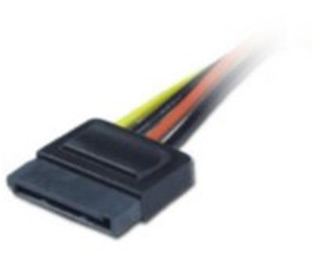
Pic. 2. SATA power cable connector.
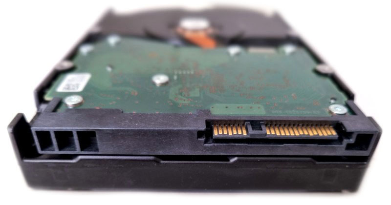
SATA data and power cable connectors are keyed to fit into the corresponding notches of the connectors on the back panel of the SATA hard drive:
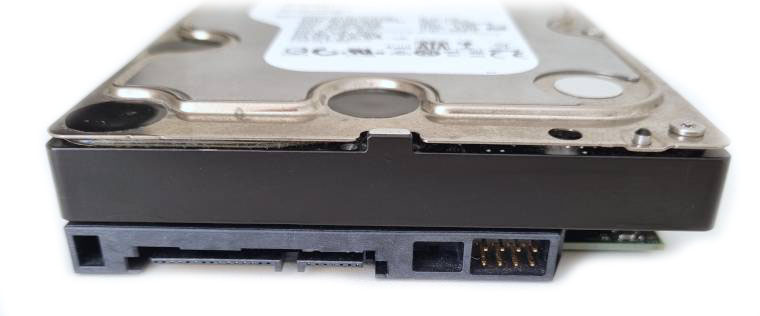
Pic. 3. Back panel of the SATA hard drive.
In this picture:
-
SATA data port. Please pay attention to the keying notch in the slot.
-
SATA power supply port. It is wider than the SATA data port and has a keying notch as well.
- USB to SATA adapter
- External drive enclosure
- Hard drive docking station
- Dedicated SATA or SAS motherboard connectors
- PCIe expansion card (SATA or SAS HBA)
SAS (Serial Attached SCSI)
SAS is the evolution of the obsolete parallel SCSI interface into the one that uses serial design and addresses its speed limitations. Hard drives based on this standard began to appear in 2004, whilst the first SSD was produced later in 2005. Nowadays, SAS still finds wide application, mostly in enterprise computing.
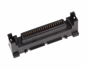
SAS uses the same pinout as SATA, but instead of two separate connectors for data and power, it has a single combined plug, with data and power delivered through the same cable.
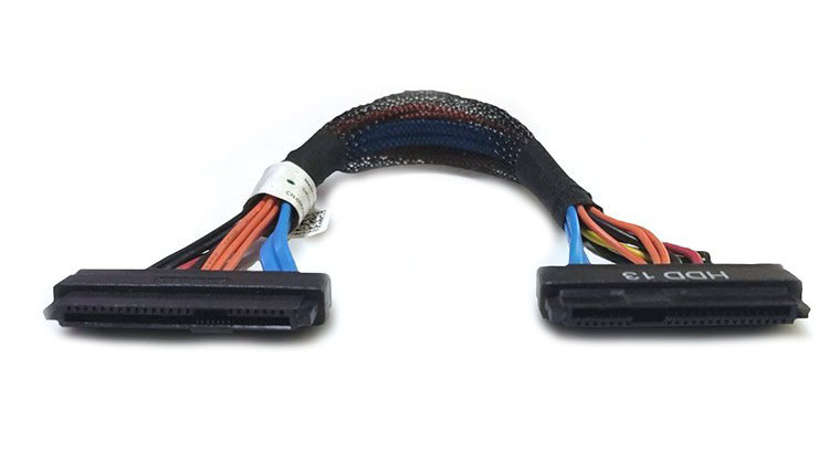
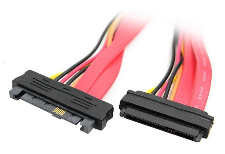
Pic. 4. SAS data and power cable.
A SAS connector is compatible with both SAS and SATA hard drives, and can host up to 16 storage devices simultaneously. Such connectors can be found on special SAS-compatible motherboards or added via a supplementary host bus adapter. However, it is not possible to plug a SAS hard drive into a SATA port because of the characteristic spacing between data and power connections in these slots.
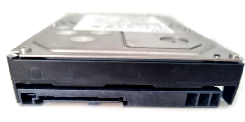
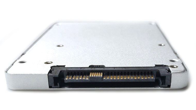
Pic. 5. Back panel of a SAS drive.
The SAS specification also offers inherent support for hot-swapping.
- Dedicated SAS motherboard connectors
- PCIe expansion card (SAS HBA)
M.2
The M.2 interface has been designed for solid-state drives housed in space-constrained devices, like laptops, ultrabooks and tablets. An M.2 SSD is a small printed circuit board with chips that resembles a stick of gum. They may have various lengths, typically 42, 60, or 80 millimeters. This type of SSD is not hot-swappable, doesn't use any cables and is inserted directly into the dedicated M.2 slot on the motherboard, held by a single mounting screw in the middle of its back side.
Depending on the version, an M.2 drive can make use of either the SATA or the faster PCIe interface. PCIe-compatible M.2 SSDs can exploit the state-of-the art NVM Express (NVMe) communication protocol. This logical interface delivers read and write speeds unattainable with the older AHCI specification, which was originally intended for slower rotating media. The M.2 drives that rely on NVMe are referred to M.2 PCIe NVMe or simply M.2 NVMe SSDs.
All M.2 drives are keyed correspondingly to prevent insertion into an incompatible socket. Each type of M.2 SSD keys is identified by its letter – B for a SATA version or M for a PCIe NVMe version. A single M.2 SATA drive can also have both B+M key types that provide its cross compatibility with both types of slots.
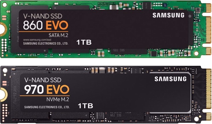
Pic. 6. M.2 solid-state drives.
- Dedicated M.2 motherboard connectors
- USB to M.2 adapter (only for M.2 SATA)
- SATA-compatible options via a SATA to M.2 adapter (only for M.2 SATA)
- USB to M.2 NVMe adapter (only for M.2 NVMe)
- PCIe 4X expansion card adapter (only for M.2 NVMe)
- U.2-compatible options via an M.2 to U.2 adapter (only for M.2 NVMe)
mSATA (mini-SATA)
mSATA is a variant of the SATA interface for SSDs adapted to be arranged inside compact devices that couldn't hold a full-sized SATA digital medium. The main difference is its smaller form factor, nearly the size of a credit card, and lower power consumption. Also, this connection does not support the hot-swap capability. In addition, like M.2, an mSATA drive doesn't need any cables. It is inserted directly into the dedicated mSATA slot on the motherboard and held by two mounting screws in the corners. Its connector is wider in comparison to M.2 and has more pins. Though mSATA SSDs can still be found in today's gadgets, they are increasingly being replaced by more modern M.2 drives.
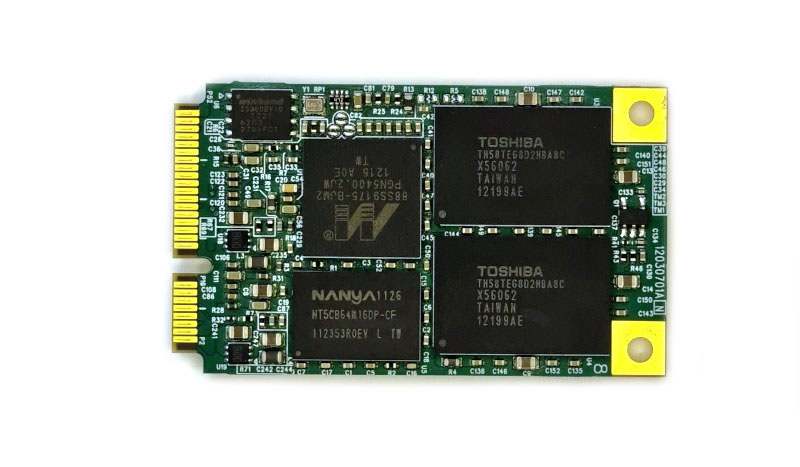
Pic. 7. mSATA solid-state drive.
- USB to mSATA adapter
- Dedicated mSATA motherboard connectors
- SATA-compatible options via a SATA to mSATA adapter
U.2 (SFF-8639)
Originally, this solid-state drive interface was called SFF-8639, but later received a more friendly name. U.2 is meant for enterprise market and delivers very high speeds of data transfer. Similarly to M.2, it works through the PCIe bus and supports NVMe, but in contrast to it, uses the traditional 2.5-inch SSD form factor and is hot-swappable. Its connector may be visually confused with SATA or SAS, yet, they have different pin configurations and are not compatible. Also, U.2 has both power and data in one cable. A U.2 connector can be distinguished by additional pins in the middle and on the back side. The wider plug goes to the drive, and the smaller one is attached to a U.2 port on the computer's motherboard.
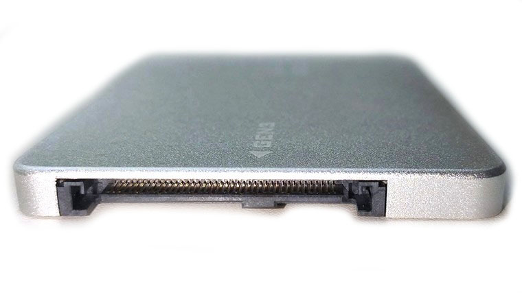
Pic. 8. Back panel of a U.2 solid-state drive.
- Dedicated U.2 motherboard connectors
- PCIe expansion card (NVMe HBA, like HBA 9400 Broadcom and higher)
PCIe (PCI-Express)
A PCIe SSD communicates with the system directly via the high-speed PCIe interface for the sake of increased performance. Its connector has a specific shape to fit into the regular multipurpose PCIe slot on the motherboard. The specification also allows hot-swapping the devices. Yet, such drives are more costly than other SSD types and used primarily in high-end servers and data centers.
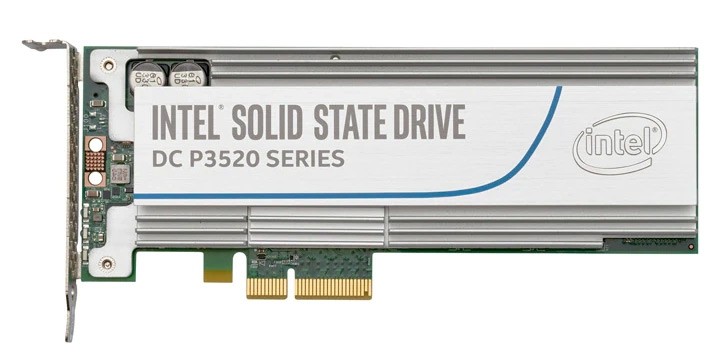
Pic. 9. PCIe solid-state drive.
- Dedicated PCIe motherboard connectors
- USB PCIe Riser adapter
FC (Fibre Channel)
FC is a high-speed technology that was initially designed for networks, but in the late 1990s started to be applied for hard drives in enterprise-level storage systems. At the beginning of the 2000s, it has migrated to SSDs as well.
Despite the name, Fibre Channel can use twisted pair copper or fiber optic cabling. Multiple drives can be connected together to form a continuous loop. A single FC bus can host as many as 126 devices. Such drives have 40-pin SCA-type connectors.
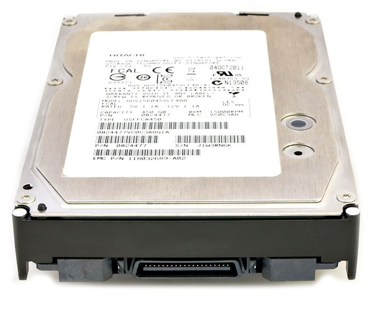
Pic. 10. Back panel of an FC hard drive.
Two cables are used for each connection: the first one carries data from the FC controller to the drive(s). A second cable carries data from the drive(s) back to the controller.
Pic. 11. Fibre Channel cable connector.
Though FC drives enable very fast data transmission and are hot-swappable, as a rule, their specificities prevent them from being used outside the dedicated infrastructure. This infrastructure is usually very expensive, and its maintenance is feasible mostly for large corporations. The majority of hardware manufacturers prefer the more universal SAS interface over FC.
- Dedicated FC backplane or enclosure
- Fibre Channel HBA and a T-card adapter
Outdated interfaces
The drives based on these interfaces are no longer in active production because they're slower, bulkier and less reliable than the current technologies. It is very unlikely to come across them in contemporary computer systems. Yet, they still can be encountered in some obsolete hardware.
IDE/ATA/PATA (Parallel ATA)
This is a legacy connection type that has been used as a standard in personal desktop and laptop computers for many years until superseded by SATA starting from 2007. In contrast to modern device interfaces that are based on serial signaling, IDE transfers multiple bits of data simultaneously, and such an approach limits its speed. Also, IDE drives do not possess hot-plug capabilities.
IDE employs 40-pin connectors located on the both sides of a flat 80-wire (newer standard) or 40-wire ribbon cable (older standard). One end of this cable with a blue connector is plugged into an IDE port on the motherboard, and the other one with a black connector – into the rear panel of the hard drive. Most IDE cables contain an additional gray connector in the middle for attaching the second drive via the same cable. The black connector at the end of the cable is referred to as a "master", and the gray one in the middle – as a "slave".
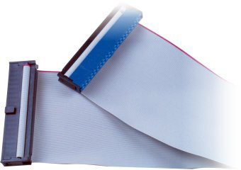
Pic. 12. IDE (PATA) data cable.
In this picture, the blue connector is used to connect the cable to the mainboard of the computer, while the black one is attached to the drive.
IDE drives are powered using a 4-pin Molex connector. The design of this connector makes it non-reversible. If you apply force and attach it backwards, you can easily destroy the device.
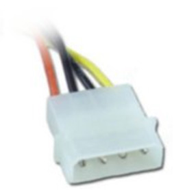
Pic. 13. Molex power cable connector.
The back panel of the IDE hard drive contains the matching slots for the keys on the IDE data and power cable connectors:
Pic. 14. Back panel of an IDE (PATA) drive.
In this picture:
-
IDE data port. Please pay attention to the small notch in the top center. It is used as an index for correct cable connection. Incorrect cable connection can damage the connector and the drive.
-
Power supply port. It also has a keyed shape for correct connection of the power cable. Incorrect cable connection can damage the connector and the drive.
-
A jumper block between the IDE data port and supply port is used for identification of the order of the drives in a paired IDE cable (master/slave) as well as for additional IDE settings.
However, some laptop IDE hard drives may not separate data and power, using 44-pin connectors instead.
- USB to IDE adapter
- Dedicated IDE motherboard connectors
- SATA-compatible options via a SATA to IDE adapter
- PCI/PCIe expansion card (IDE HBA)
SCSI
SCSI wasn't designed specifically for hard disk drives, but rather for peripherals in general, including printers, scanners, СD-ROMs and others. Yet, it was very common for hard drives used in computers and servers from 1986 up to the early 2000s. Later, SCSI drives started to be replaced by more efficient and reliable SAS drives. SCSI transmits multiple data bits concurrently rather than one at a time and supports hot-plugging operations.
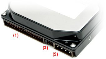
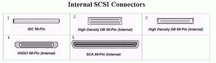
Depending on the version, SCSI may use 50-pin, 68-pin or 80-pin connectors and flat ribbon cables to send and receive data and power to internal SCSI devices. One end of the cable is plugged into a socket on a SCSI-compatible motherboard or an additional host bus adapter, and the other end is plugged into a hard disk drive or other peripheral device. External devices are attached with a thick round cable in a daisy chain. The first version of SCSI supported up to eight devices (narrow bus), while the subsequent ones could host up to 16 (wide bus). The number of SCSI variations, which are often incompatible with one another, often makes it difficult to recognize this type of interface.
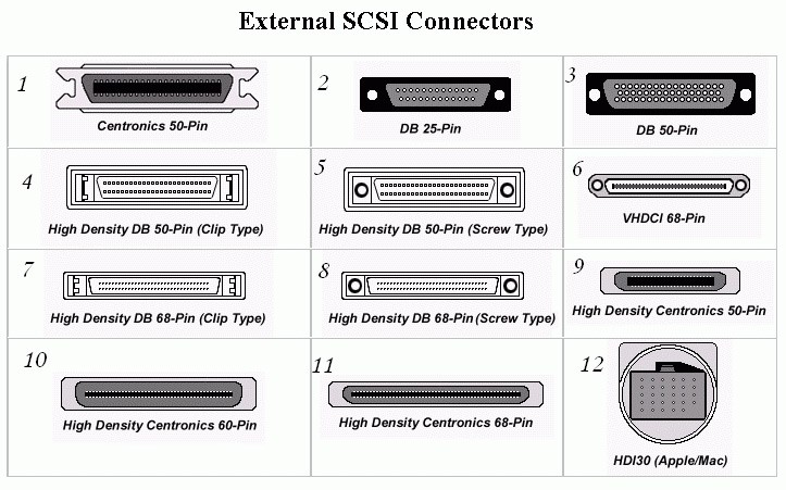
Pic. 15. Different types of SCSI connectors.
Internal SCSI devices have a single port attached to a ribbon cable with multiple connectors. By contrast, external devices have two ports, one for the incoming cable and the other one for the cable that goes to the next device.
Pic. 16. Back panel of a SCSI drive.
Each SCSI device has its own unique ID number configured by adjusting jumpers on it that determine its order. Once the devices are installed, each end of the bus has to be terminated with a resistor circuit. Some SCSI terminators are built into the SCSI device, while others may require an external terminator.
- Dedicated SCSI motherboard connectors
- PCI/PCIe expansion card (SCSI HBA)
Vendor-specific interfaces
Solid-state drives used in Apple products starting from 2010 usually have proprietary connectors and form factors that differ from the ones provided by other manufacturers. They may bear resemblance to some of the above-described standards, but still have different pin arrangements, varying from one model to another.
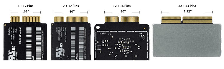
Pic. 17. Apple SSD connectors.
- USB adapter designed particularly for the respective connector
- Motherboard connectors of other types (SATA, M.2, etc.) via a specialized adapter
Choosing the method of connection to the computer
There are several methods you can apply to attach a drive to the computer, both internally and externally. The choice of a proper one should depend on the type of interface used by the storage device, your budget, and, of course, the level of your technical skills. At the same time, please mind that external methods, despite being more convenient, may significantly limit the speed of connection.
USB adapter
This is one of the safest but relatively expensive methods. You will need a special USB adapter (converter) for each drive to connect them to the computer as if they were portable external devices. One end of the adapter should be plugged into the computer's USB port, and the other one is attached to the drive. If you want to maximize the speed, go for USB 3.0 and higher. In case your computer lacks a USB port, you may look for other options compatible with your machine, for instance, FireWire or Thunderbolt.
In theory, it is possible to find such adapters for the majority of drive interfaces. Yet, some of them, like USB to SAS or USB to U.2 are quite uncommon and may be very costly, since they have to include the entire controller for the respective interface to make the drive work.
USB to SATA and USB to IDE adapters are the most prevalent on the market. Certain models may even combine both connection types.
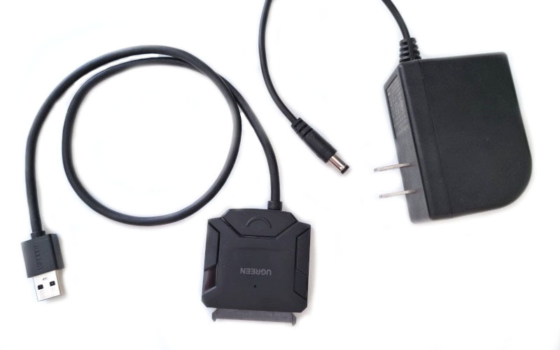
Pic. 18. USB to SATA hard disk adapter with an external power supply.
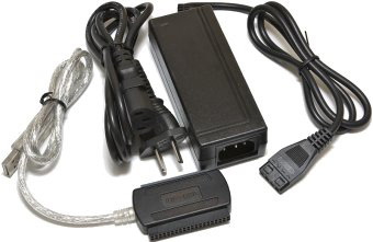
Pic. 19. USB to IDE hard disk adapter with an external power supply.
Average USB converters for M.2 are designed for use only with the SATA version of this interface and thus accept drives with B or B+M keys. PCIe NVMe drives with an M key type cannot be connected via them and require special USB to M.2 NVMe adapters. Yet, it should be pointed out that even such solutions may still be unable to handle specific SSD technologies, like Intel Optane.
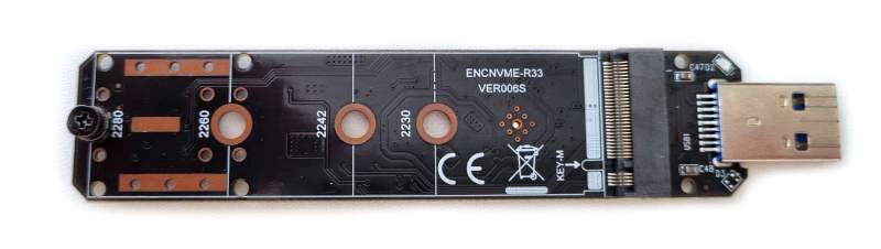
Pic. 20. USB to M.2 NVMe adapter.
PCIe SSDs can be connected via USB using a PCIe Riser adapter designed for graphics cards.
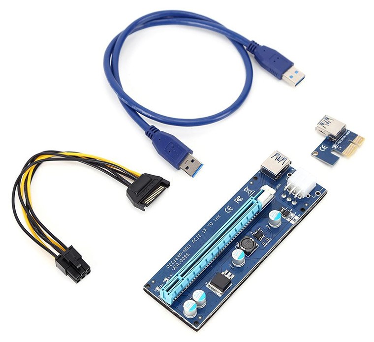
Pic. 21. USB PCIe Riser adapter.
USB adapters for certain popular Apple drive connectors may be available on some marketplaces. However, before making a purchase, it is important to check the device description carefully and verify its correspondence to the Mac model and year of its release.
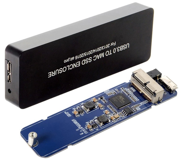
Pic. 22. USB adapter for Mac SSD.
Some adapters may provide multiple connectors for the same interface type, thus, you can use such an adapter to connect several hard drives at a time. Alternatively, if the host computer has enough storage space, you can create an image of each drive one by one with the help of a single adapter and thus avoid connecting them simultaneously.
However, ensure that you get an adapter with the correct connector that exactly matches the pins arrangement of your drive. Check its specifications related to the maximum capacity of drives that can be hosted. Older USB 2.0 adapters normally do not work with drives over 2 TB, whereas newer USB 3.0 and higher may support drives up to 6 TB.
Also, pay attention to the power supply: some adapters may be powered via USB and require an additional external power source for 3.5-inch drives, in contrast to 2.5-inch ones that consume less electricity.
Hint: The implementation of this method is demonstrated in the tutorial on connecting SATA disks with the help of a USB to SATA adapter.
External drive enclosure (case)
This method is costly and similar to the one described above, except the adapter is designed as a physical case that houses and powers the hard drive. Such an enclosure may have one or more ports, using which it can be connected to the computer via a USB cable (or FireWire, Thunderbolt, etc.). Most drive enclosures can take a single drive, but there are also models with multiple bays in which more drives can be inserted. The latter may even have their own cooling fans.
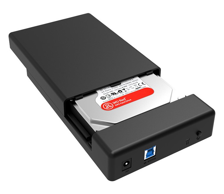
Pic. 23. External single-drive enclosure.
This method offers even more security, as a metal or plastic housing covers the digital medium, protecting it from damage. However, enclosures for drives with certain connector types may be rare and quite hard to find. Another important thing is to pick out one that supports your drive's capacity and matches its form factor. Some enclosures can hold both 3.5-inch and 2.5-inch drives, and there are also models for particularly shaped SSDs, like mSATA or M.2. Drive enclosures for M.2, similarly to USB adapters, work with either SATA or NVMe SSDs.
Hint: Please rely on the tutorial to learn how you can connect SATA drives with the help of an external enclosure.
Hard drive docking station
A hard drive docking station is a variant of an external enclosure. Such a unit has a top-loading design and is situated on the desktop. Drives are installed into it in an upright position and can be ejected more easily with the push of a button. Most docking stations are dual and have two drive slots, but some of them can accommodate as many as six drives.
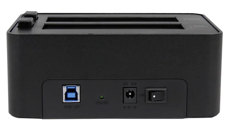
Pic. 24. Hard drive docking station.
However, these devices are mostly designed for traditional 2.5-inch and 3.5-inch SATA hard drives. Some other interfaces may be available, but they are much more difficult to purchase.
Dedicated motherboard connectors
This is the cheapest but one of the most unsafe methods to connect the drives. In order to employ it, you need to be sure that the motherboard is compatible with the given type of hard drives. Besides, the mainboard usually has a very limited number of connectors and may be unable to place many of them. If you decide to free up some slots for extra drives, see to it that you don't unplug the system boot drive or RAID. Also, it is crucial to make sure that the computer's power supply provides at least 15 watts of additional power per drive.
To check if the method is suitable, examine your motherboard connectors. To do this:
-
Remove the screws from the back panel of your computer that hold the case. Removing two screws that hold the left-side cover is enough (for a tower-type computer).
-
Open the left cover panel: pull it a little back and put it aside.
-
Examine the slots on the mainboard.
For SATA drives. This type of drives are probably the most easy to handle, as the overwhelming majority of computers sold today have motherboards that support the SATA interface. There should be L-shaped ports similar to the following ones:
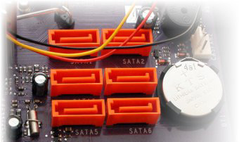
Pic. 25. SATA ports on the motherboard.
They are usually black, red or orange and are numbered as SATA1, SATA2, etc. Each of them is capable of hosting one SATA drive. In most cases, all of them have a uniform color, but some motherboards may have differently colored SATA ports indicating several SATA generations. Every newer generation offers higher transfer speed compared to the previous version. The number of SATA ports may vary from motherboard to motherboard, but a typical design usually includes from 4 to 6.
Another important port for SATA connection is a power port, which comes from the computer's Power Supply Unit. If you need to power more SATA drives, you may split a single port into two or more connectors using an additional SATA power splitter.
Also, see to it that you have a sufficient number of cables – one SATA data cable and one SATA power cable per each SATA drive.
Besides SATA ports, the drives of this type can be attached to SAS connectors, if they are available on the motherboard. This is possible thanks to the backwards compatibility of the newer SAS standard, but doesn't work the other way around.
Hint: Please find an instruction that will help you to connect SATA drives directly to the computer's motherboard.
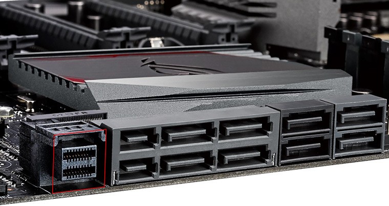
For SAS drives. The main drawback of SAS drives is the lack of support for them in consumer hardware. Even though SATA drives are compatible with the SAS interface, a SAS drive can in no way be plugged into the prevailing SATA connectors. Only special server-class motherboards with an in-built SAS controller and unified 80-pin ports are suitable for this type of drives. That is why you should determine whether your motherboard includes a SAS chip, which is highly unlikely for a conventional PC. Also, you will need the appropriate SAS cable to connect the drive to it.
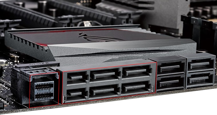
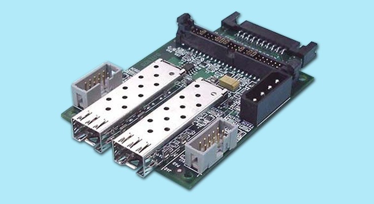
Pic. 26. Ports for SAS Drives on the motherboard (miniSAS HD & SATA Express).
In case of lack thereof, you will have to add a SAS controller to your system as a SAS HBA expansion card, which is another method explained further in this article.
For M.2 drives. M.2 SSDs have become common only within the last few years, so you need to ensure the motherboard offers a small horizontal elevated connector for this new-generation drive.
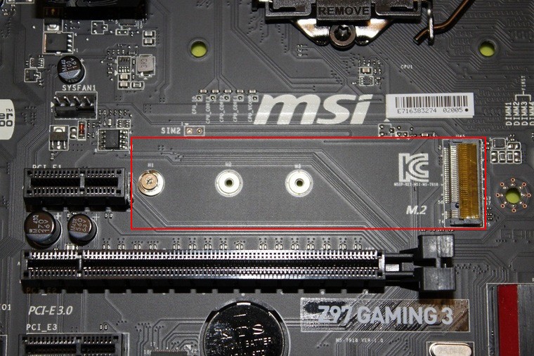
Pic. 27. M.2 slot on the motherboard.
If it does, the next thing to find out it is whether this slot is compatible with the M.2 drive you have. This is where the type of connector's key plays a role. It must match the type of slot in which you are going to insert it. An M.2 SATA SSD with a B-key can fit only into a B-type SATA slot, whereas an M.2 PCIe NVMe SSD with an M-key belongs only to an M-type PCIe slot. Yet, if the drive is equipped with a B+M key, it can be plugged into both interfaces.
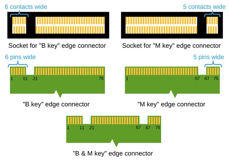
Pic. 28. M.2 key and slot types.
Another important aspect to keep an eye on if there is enough physical space to place the storage device, since M.2 drives vary in their lengths.
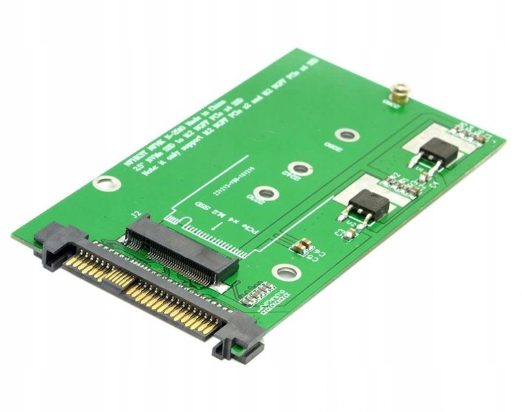
A SATA variant of M.2 SSD can also be installed into a SATA port on the motherboard if used in combination with a SATA to M.2 adapter. The same shall apply to other methods of connection suitable for SATA.
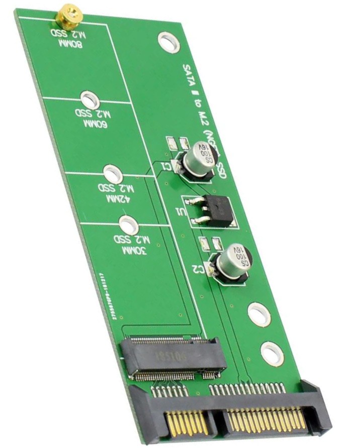
Pic. 29. SATA to M.2 adapter.
M.2 PCIe NVMe drives are not compatible with SATA, but can be operated via a U.2 connector when attached to an M.2 to U.2 adapter.
Pic. 30. M.2 to U.2 adapter.
An alternative option to connect an M.2 PCIe NVMe SSD is to use a PCIe 4X expansion card adapter.
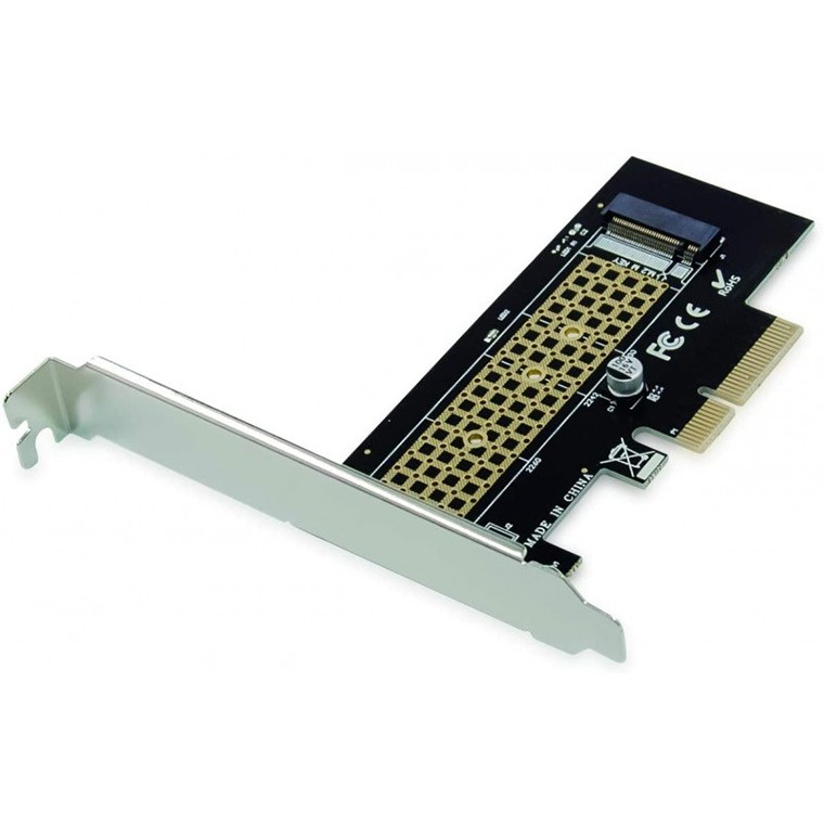
Pic. 31. PCIe 4X expansion card adapter.
However, it should be noted that direct methods of connection are inadvisable for M.2 PCIe NVMe drives when they have any signs of hardware issues. When a defective storage is attached to the M.2 or PCIe slot on the motherboard, it may stop responding and cause the entire system to freeze. Under these circumstances, the use of a USB adapter or enclosure is much more preferred.
Apart from that, an M.2 PCIe NVMe SSD attached to an M.2 motherboard port is able to operate in both SATA and PCIe modes. The mode defines the speed of the drive and can be switched in the BIOS settings. Therefore, if the speed is too slow, you should make certain that the correct mode is selected.
For mSATA drives. mSATA drives absolutely differ from their SATA predecessors in their physical form factor and connector. Despite that, the mSATA interface uses the ATA commands set, just like SATA. Hence, if you cannot locate an mSATA socket on the motherboard of your computer, you can attach an mSATA drive to a standard SATA port using a SATA to mSATA adapter. However, check the specifications carefully to see that it is compatible with your particular mSATA drive.
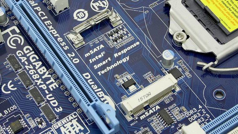
Pic. 32. mSATA slot on the motherboard.
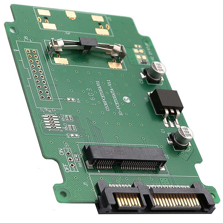
Pic. 33. SATA to mSATA adapter.
For U.2 drives. Similarly to the previously mentioned drive types, U.2 requires specific motherboard support. Thus, you should check whether there is a respective U.2 drive slot. This interface was developed for mostly for enterprise use, but it can also be included in some high-end PCs. Furthermore, you will need to prepare a single cable which carries both power and data.
Pic. 34. Ports for U.2 Drives on the motherboard (miniSAS HD SFF-8643).
Such a device may also be connected to an M.2 port with the help of a special M.2 to U.2 adapter.
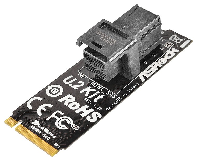
Pic. 35. M.2 to U.2 adapter.
Another possible way to connect a U.2 SSD is to use an NVMe HBA card. This method is described further in this article.
For PCIe drives. Such drives possess their own controllers built into the SSD chipset. Therefore, they require only a standard multipurpose PCIe connector to be available on the motherboard. In addition, a SATA power cable is necessary to plug the drive into the computer's supply.
Pic. 36. PCIe port on the motherboard.
For FC drives. Despite using SCSI commands set, FC drives communicate through a Fibre Channel Protocol and cannot operate without a special Fibre Channel controller. Also, an appropriate FC enclosure is required to connect and power the drive. Otherwise, you may use an FC HBA and a special T-card adapter per each drive to convert the drive's 40-pin SCA connector to separate FC port and power DC connectors. Also, you will need an SFP cable and a power cable.
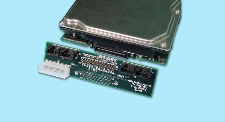
Pic. 37. T-card adapter for a Fibre Channel drive.
For IDE drives. It's quite rare to come across a computer with a motherboard that that holds IDE ports, as they have been mostly replaced by the SATA standard. But if you find an old PC, chances are that its motherboard has some wide 40-pin IDE sockets, like these:
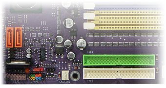
Pic. 38. IDE ports on the motherboard.
In this picture, you can see two IDE sockets marked as IDE 1 and IDE 2 at the right bottom. As a rule, IDE 1 is colored, while IDE 2 is usually black or white. Each IDE channel is capable of hosting two IDE hard drives – the "master" should be placed in the middle of the IDE data cable, and the "slave" is connected to the cable's end. The device must also be configured as the "master" or "slave" with the help of a jumper, depending on its position on the cable.
The power supply of such a computer should contain 4-pin Molex power connectors. If the number of such connectors is smaller than the number of IDE drives, you can use Molex power splitters.
In addition, ensure that you have one IDE data cable per each pair of IDE drives and enough cables to power them.
If you have just a SATA motherboard, you can still connect an IDE drive to it if you purchase an additional SATA to IDE adapter, and, if necessary, an adapter for the drive's 4-pin Molex power connector.
For SCSI drives. Similar problems can be faced if you need to attach older SCSI drives. The situation is also aggravated by versatility of the SCSI standard. Since the interface has evolved much over the years, it is possible to encounter a great many of different SCSI connector types. Thus, even if you happen to find a motherboard with the SCSI support, ensure that it is indeed compatible with the interface version used by the drive or find a relevant adapter.
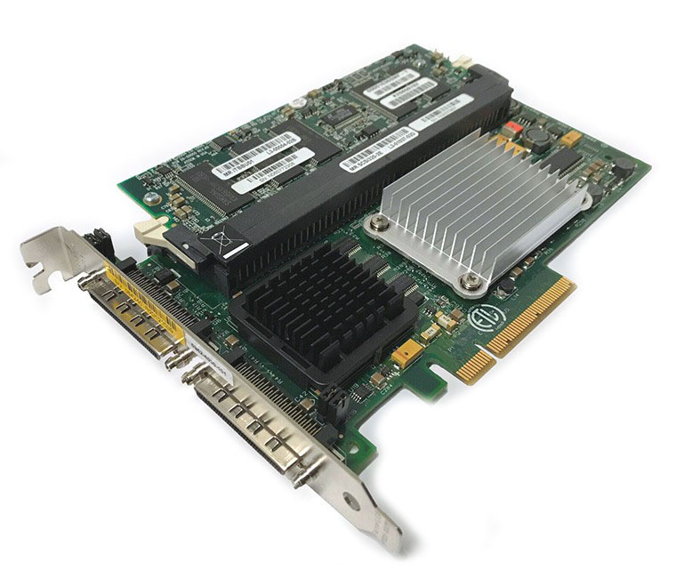
Pic. 39. SCSI ports on a RAID controller.
Besides appropriate cabling, each drive on an old SCSI bus must be assigned an individual ID for correct identification. A SCSI controller usually has a zero ID, so each drive should have a subsequent ID number set up via jumpers at the back pane. Also, to enable proper communication, the end of the SCSI bus needs termination. Therefore, see to it the last drive on the cable is terminated using a jumper/switch built into it or connect an external terminator to the end of the cable.
In general, a more preferred way for connection of such a drive is to use an expansion card with a SCSI interface that is plugged into a PCIe slot. Also, newer SCAM-compliant host bus adapters and drives contain special firmware capable of the SCSI drive's ID and termination status automatically.
For vendor-specific SSDs. It may be highly problematic to use this method for drives that belong to Apple devices, especially their modern versions. In the majority of cases, they feature interfaces that differ from the industry standard connectors utilized in other computers. Even more, the SSDs may be incompatible between different releases of the same model. Connecting such a drive to the motherboard may be possible if you find an appropriate adapter that will enable it communication with some common slot type, for instance, SATA or M.2.
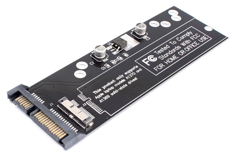
Pic. 40. SATA to Apple SSD adapter.
Besides compatibility, many Macs have their internal drives soldered to the mainboard, which makes them impossible to remove.
PCIe expansion card
Should you discover that your mainboard doesn't provide the necessary connectors, it is possible to upgrade it through the universal PCIe interface available on most modern motherboards. The slot is commonly used for graphics or sound cards, network adapters and similar high-speed devices. Among other things, it can accommodate a special expansion card that will add an extra controller and ports to your system. These are also referred to as PCIe HBA cards. There are different types of them, depending on the actual interface they host. Sometimes they have RAID capabilities, but as this functionality is not required, it will be more reasonable to opt for a more budget non-RAID HBA.
The method of connection is quite efficient, however, is not 100% safe. Before choosing it, ensure that the computer's power supply is capable of providing at least 15 watts of additional power per drive, plus about 10 watts for the PCIe HBA card.
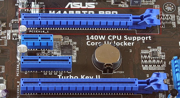
An expansion card can be installed to any free PCIe slot on the mainboard, or, sometimes, to an older PCI bus. If necessary, the slot can be converted from one standard to another via the corresponding adapter.
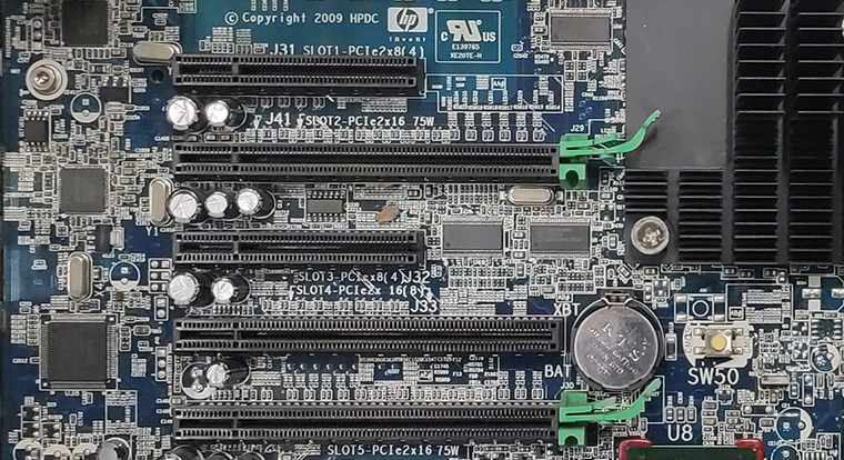
Pic. 41. PCIe slots on the mainboard.
PCIe SATA HBA cards have two or more SATA sockets. Each socket is capable of hosting one SATA drive. It's recommended to use one card for all the drives. But as multi-port cards are more expensive, you may consider using several cards to save costs.
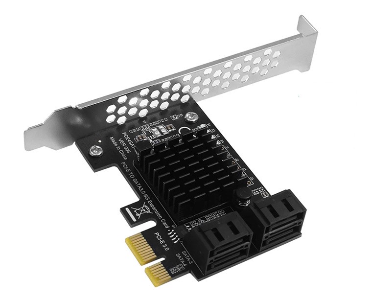
Pic. 42. PCIe SATA expansion card.
SAS HBA cards, like LSI/Broadcom, are typically more expensive. They may have two or more SAS channels. Each of the ports may host one SAS drive or up to four SATA drives per channel.
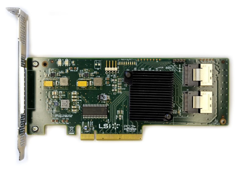
Pic. 43. PCIe SAS/SATA expansion card with miniSAS SFF-8087 ports.
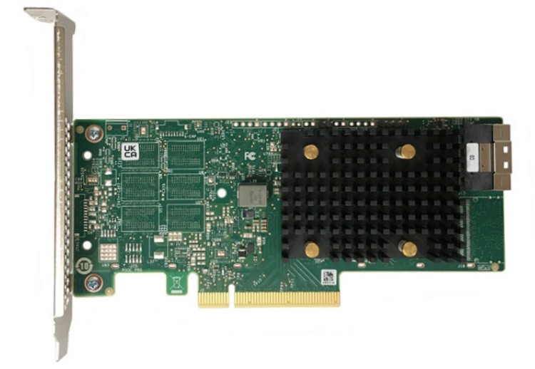
Lately, NVMe HBA models with PCIe ports have also appeared, which support the connection of U.2 drives, like Broadcom HBA 9400 series or higher. Such cards are also able to host M.2 NVMe drives via an adapter.
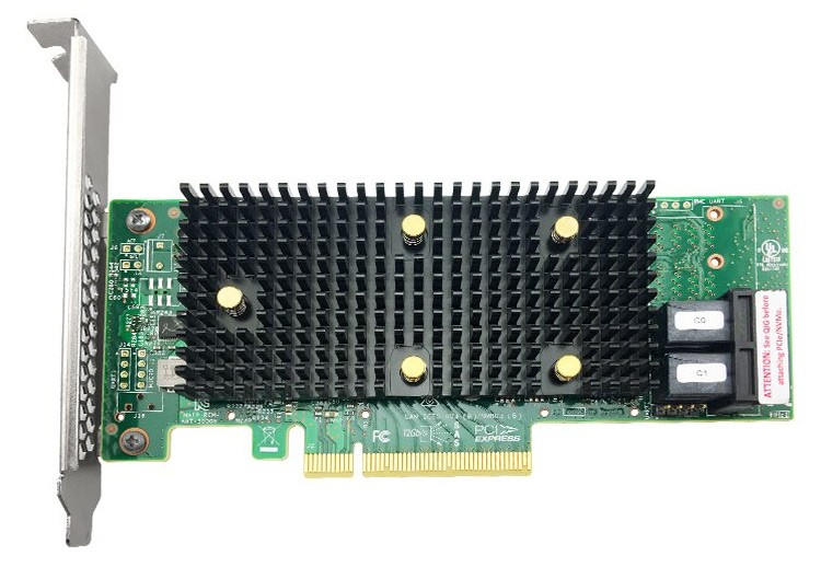
Pic. 44. Broadcom HBA 9400-8i.
Pic. 45. Broadcom HBA 9500-8i.
A U.2 drive can be connected to the HBA via a special a U.2 enabler cable – with a 1x8 Mini SAS HD (SFF-8643) connector on the PCIe adapter side for Broadcom 9400, or 1x8 SlimSAS (SFF-8654) connector for Broadcom 9500.
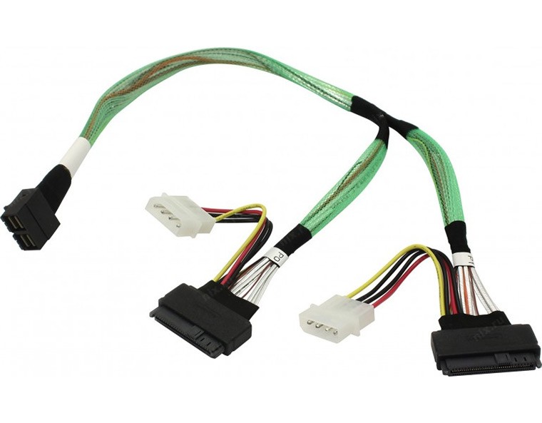
Pic. 46. U.2 enabler cable for Broadcom 9400 Series.
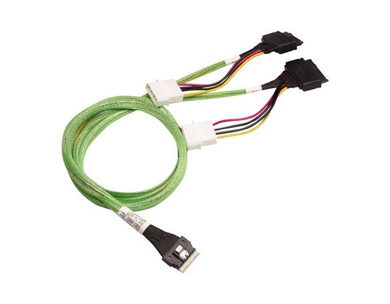
Pic. 47. U.2 enabler cable for Broadcom 9500 Series.
Also, the PCIe channel has to be reserved for the U.2 drive, so you will need to restart the card after the storage medium is attached.
PCIe IDE expansion cards have one or more IDE ports. Each port is capable of hosting two IDE drives. It is recommended to use one card for all the drives.
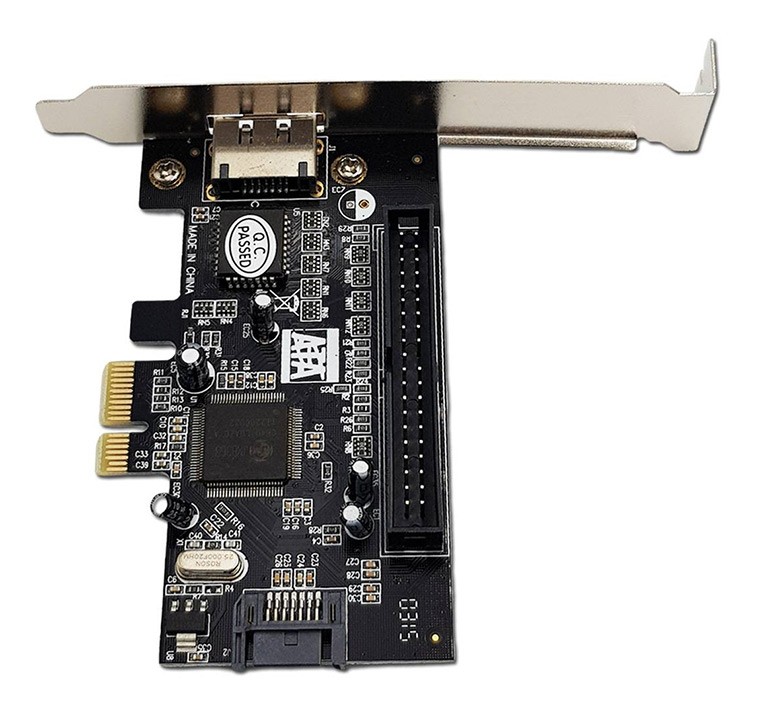
Pic. 48. PCIe IDE expansion card.
PCIe SCSI expansion cards have one or more SCSI ports. Each port is capable of hosting up to 15 SCSI drives. It is recommended to use one card for all the drives. You may also need additional adapters in view of the diversity of SCSI connectors.
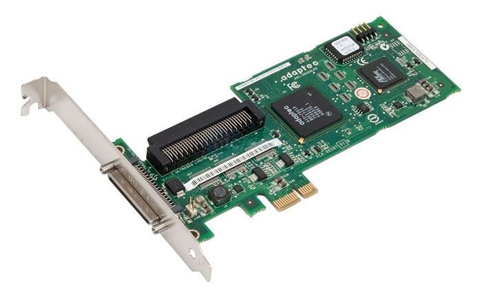
Pic. 49. PCIe SCSI expansion card.
Certain expansion cards for IDE or SCSI drives may feature the legacy PCI interface instead of PCIe. Though the standard is not backwards compatible, it is still possible to attach a PCI card to a modern motherboard with the help of a PCI to PCIe converter.
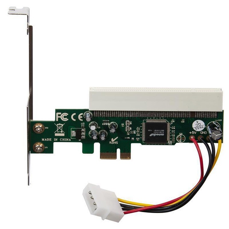
Pic. 50. PCI to PCIe adapter.
On the whole, before getting an PCIe expansion card, it should also be taken into account that old HBAs do not support long logical bit addressing due to the 32-bit LBA limit, which makes them unable to handle individual drives larger than 2 TB in capacity. Also, make sure that the expansion card kit contains a sufficient number of cables. You might also need to purchase additional ones.
Hint: Please refer to the installation manual of an expansion card for more details.
After the installation of additional external adapters, expansion cards, hard disk drives, etc., you may proceed to logical data recovery using the instructions that correspond to your particular case.
Note: If the hard drive shows any signs of hardware defects, please, familiarize yourself with the peculiarities of work with damaged drives.
Last update: November 15, 2022