Identification of the drives' order in an XFS-based NAS
By and large, NAS units, like Buffalo LinkStation and TeraStation, Iomega StorCenter and Synology, make use of software RAID built from data partitions (the largest partitions) of each of the drives constituting the storage. Then the XFS file system is distributed across these data partitions. That being so, to be able to properly assemble a RAID configuration for further data recovery, users need to know the correct order of the drives that comprise the RAID system the NAS box relies on.
The article below explains how one can identify the order of the drives in a four-disk XFS-based NAS of Buffalo TeraStation, Iomega StorCenter, Synology and similar NAS models.
Ways and means
Before starting to recover data from an XFS-based NAS, one should find out the order of the RAID drives and RAID parameters.
One possible method to identify the order of the drives is to analyze their hexadecimal content in accordance with known data fragments at the beginnings of data partitions. Effective means for such analysis are provided by CI Hex Viewer. At the same time, some advanced data recovery applications offer a much easier way to identify RAID parameters – automatic RAID detection.
As a rule, NAS devices don't allow direct low-level access to their file systems and XFS-based NAS solutions are not an exception. Thus, you should disassemble the storage and connect its drives to a PC. Please read How to connect IDE/SATA drive to a PC for recovery for detailed instructions. Also, you can rely on the provided video tutorials to plug the drives into the motherboard of the computer or connect them externally using a USB to SATA/IDE adapter.
Automatic detection of RAID parameters
XFS-based Network Attached Storages usually apply Multiple Devices (MD) software RAID configurations. Such RAID configurations are created with the help of the well-known mdadm utility and include linear (JBOD), stripe (RAID 0), mirror (RAID 1), RAID 5 and RAID 6 configurations. This utility creates pseudo-partitions with metadata sufficient to build RAID automatically.
SysDev Laboratories offers UFS Explorer software as powerful utilities which support automatic detection, reconstruction and data recovery from software RAID. UFS Explorer RAID Recovery was specially developed for work with complex RAID systems while UFS Explorer Professional Recovery presents a professional approach to data recovery from various devices, including RAID sets of different complexity. For more detailed information, please, consult with the technical specifications of the corresponding product.
To build RAID automatically with the help of UFS Explorer RAID Recovery one should:
- Download, install and run the software;
- Connect the NAS drives to the host computer or open disk image files in the interface of the program;
- The software will assemble RAID automatically and add the storage to the list of devices for further operations.
If automatic RAID detection is turned off in the program settings, one should:
- Open RAID Builder, select any data partition of the software RAID and add it as a component of a virtual RAID
- Once the partition is added and MD metadata is detected, the software will ask whether it should assemble the RAID automatically;
- Press 'Yes' and the program will load disk partitions in the correct order and with correct RAID parameters;
- Press 'Build this RAID' to mount this RAID in UFS Explorer for further operations.
Note:If RAID parameters of the NAS were reset to a different RAID level, drive order or stripe size, the previous RAID configuration requires manual definition. Press 'No' in the software dialog, refuse automatic RAID assembly and use the manual specification of RAID parameters.
Analysis of the content of the drives
Another way to determine RAID parameters and precisely identify the order of the drives in RAID is to conduct in-depth analysis of the content of the drives. CI Hex Viewer provides effective means for qualitative low-level analysis of data.
To prepare for the procedure one should carry out the following actions:
Linux users: do not mount the file systems of NAS drives!
Mac users: avoid any diagnostics, repair and similar operations on disks using the Disk Utility!
- Boot the PC, install and run CI Hex Viewer;
Windows XP and earlier: run the software as an Administrator;
Windows Vista/7/8/10 with UAC: run the software as an Administrator using the context menu;
macOS: sign in as the system Administrator when the program starts;
Linux: from the command line run 'sudo cihexview' or 'su root -c cihexview'.
- Click "Open" and then choose "A physical disk"(Ctrl+Shift+"O"); open the data partition of each NAS drive.
Each NAS drive has the same partition structure: 1-3 small "system" partitions (with the total size of about several gigabytes) and a large data partition (usually over 95% of the total capacity of the drive). For further information about the layout of the partitions, please read the given article.
RAID configuration and advanced detection of the order of drives
To start analyzing the content of drives, open the hexadecimal view of each data partition of all the NAS drives in CI Hex Viewer.
You can see an example of content analysis for a default RAID 5 configuration with the 64 KB stripe size and the XFS file system.
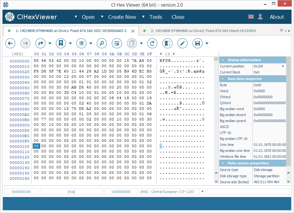
The starting block (or the superblock) of the XFS file system contains an "XFSB" string at the start, values of file system parameters and many zeros. A valid superblock never contains any non-zero data at a range from 0x100..0x200 bytes. This property makes it easy to determine the validity of the superblock.

In this XFS file system the I-nodes block is found at an offset of 64 KB. In the RAID 0 and RAID 5 layouts with the default 64K stripe size the I-nodes block is located at a zero offset of the data partition of Drive2.
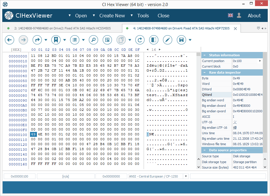
I-nodes can be identified by the "IN" string ("49 4E" byte sequence) at the start of each 256 (0x100) byte blocks. Each I-node describes a file system object.
The upper digit of the third byte defines the type of the object. 4X byte indicates a directory and 8X – a file.
In Figure 2 the first I-node indicates a directory and the second one – a file.
The parity block contains a mixture of data from data blocks of other drives. It may look like "trash" with visible fragments of data from data blocks.
Even if the parity block contains a valid "XFSB" string, unlike the superblock, it contains non-zero data at 0x100...0x200 bytes range; that makes it different from the superblock. Please also note that the parity block usually contains much more non-zero bytes.
Now, using this known content and assuming that the starting block is the first block of the data partition of the given drive, you can define the RAID configuration:
RAID 5:
- Only one first block will contain the superblock (Fig.1);
- If the stripe size is 64 KB (usual for TeraStation), one of the first blocks will contain I-nodes; the first I-node indicates a directory (the root directory). If the root directory contained few files, their names are given in the I-node body (as in Fig.2);
- The starting block of the third drive will contain the data or I-nodes table;
- The starting block of the fourth drive will contain parity (Fig. 3);
- Applying the XOR operation to bytes from the starting blocks of each disk at the same byte position gives zero result.
One can define the RAID 5 configuration as RAID with only one superblock in the starting block and parity. The XOR operation over the bytes of each starting block at the same byte position gives zero result.
The order of the drives is as follows: the drive with the superblock is the first one; the drive with the root directory – the second; the drive with parity – the fourth; the remaining drive – the third. The parity check procedure includes the following steps:
- Choose a partition offset with non-zero data;
- Run a calculator (e.g. Windows standard calculator);
- Choose 'View' as 'Scientific' or 'Programming', switching from the 'Dec' to the 'Hex' mode;
- Type in the hexadecimal digit from the first drive and press the 'Xor' button;
- Type in the hexadecimal digit from the next drive at the exactly same offset and press 'Xor' again;
- Repeat the procedure till the last drive. Before you enter the digit from the last drive, the calculator must show the same number as at the specified position of the last disk. The 'Xor' operation will give zero.
A non-zero value for any of the offsets indicates either a calculation error or absence of parity.
RAID 0:
- Only one first block contains the superblock (Fig.1);
- If the stripe size is 64 KB (usual for TeraStation), one of the first blocks will contain I-nodes; the first I-node must indicate a directory (the root directory). If the root directory contains files, their names are given in the I-node body (as in Fig.2);
- Other first blocks do not contain other superblocks or parity;
- Other drives may contain more I-nodes in the first block.
One can define the RAID 0 configuration as RAID with only one superblock in the starting block and without parity.
The order of the drives is the following: the drive with the superblock is the first one; the drive with the root directory is the second one. The 3rd and the 4th drives cannot be identified at once, but you can try both and find out which of them is the right one.
RAID 10/0+1:
- The first blocks of two drives contain a valid superblock (Fig.1);
- Other two drives contain data in the starting block and in case of the 64 KB stripe size – I-nodes.
One can define the RAID 10/0+1 configuration as RAID with two superblocks in the starting blocks.
The order of the drives is as follows: the drive with the superblock is the first one, the drive without a superblock (data or I-nodes) – is the second one. This configuration has two such pairs and both of them can be used for data recovery.
RAID 1 and multi-part storages:
- First blocks of each drive contain a valid superblock (Fig.1).
One can define RAID 1 and a multi-part storage as RAID with superblocks in all the starting blocks.
The order of the drives is the following: Any drive from RAID 1 gives all the data. In case of a multi-part storage each drive has a separate valid file system.
If the analysis procedure gives a contradictory result and you are still unsure about the order of the drives, try all combinations and choose the matching one.
Note: UFS Explorer software doesn't modify the data on the storage. You can try different RAID combinations until you get the appropriate one.
Final notes
Having figured out the correct RAID configuration applied to the NAS drives, one can get on with the data recovery procedure itself. The whole process is explained step by step in the NAS recovery manual and demonstrated in the NAS recovery video guide.
However, in case of physical damage, in order to avoid data loss, it is strongly recommended to bring your NAS to a specialized laboratory for data recovery.
If you feel unsure that you can conduct data recovery operations by yourself or have doubts concerning the RAID configuration of your NAS, do not hesitate to turn to professional services provided by SysDev Laboratories.
Last update: August 19, 2022