Choosing a method for connecting SATA drives to a computer
Despite the ongoing development of drives and their interfaces, Serial ATA (SATA) remains the most widely used option for connecting them to the motherboard. The majority of hard disks and even some SSDs available for purchase are still fitted with SATA ports, not to mention slightly older equipment. Such storage devices are supposed to be installed internally, straight into the compatible mainboard socket. Yet, when the original computer gets affected by data loss, it may become necessary to remove the medium and attach it to another working system for recovery. In this case, the task can be approached in several ways, depending on the specific circumstances. Here you can learn about the methods suited to plug a SATA drive into a different PC and choose an optimal one for your needs.
Hint: Please rely on the article on the identification of a hard drive’s interface type to aid you in determining whether your hard drive features SATA or some other type of connector.
Choosing between internal and external connection
As has been mentioned, SATA drives are actually made for the internal use. Still, they can also be attached externally when the situation demands. There are a few things to be considered when deciding which of these connection types is more suitable:
-
The possibility to disassemble the computer’s case.
The vast majority of PC cases can be taken apart easily using thumbscrews or a screwdriver. Yet, removing the cover and getting inside may be not desirable for the devices under warranty. It’s quite common for manufacturers to put in special seals or labels that shouldn’t be damaged to keep the warranty in effect. Also, certain casings may have a fixed design that makes them hard or even impossible to dismantle.
-
The amount of room in the chassis for the installation of additional components.
This may not be a problem for a regular tower PC. However, compact devices, like laptops or ultrabooks have strict space constraints and rarely can place any extra drives. The maximum they offer is a second drive bay for a smaller 2.5-inch SATA drive, but even these are rather infrequent.
-
The availability of vacant SATA slots in the host system.
Even when there is some space for the drives to be added, the respective number of SATA sockets should also be present on the motherboard – one slot for each SATA drive. In their absence, it may be still possible to attach the drives internally, but the mainboard should be upgraded in this case via a special expansion card that plugs into its PCI Express port.
-
The amount of additional wattage that can be delivered by the system’s power supply unit.
Any SATA drive draws a certain amount of electrical power to operate. Mechanical HDDs consume more, about 15 watts per drive. SSDs keep power consumption at a minimum, but even they should be provided with up to 5 watts. When the drives are connected internally, this energy will be derived from the computer’s PSU. It is not recommended to push the power supply beyond its maximum specifications, as this may lead to any sorts of issues, from its shutdown to a total failure. Besides, if an expansion card is employed in the assembly, the board itself will also draw between 10-20 watts that should also be taken into account.
-
The expected speed of connection.
Designed specifically for such drives, internal SATA slots on the mainboard typically outperform external ports and adapter chips used for communication. For instance, the latest SATA3 generation is capable of running at the rates of up to 6.0 GB/s. USB 3.0, which tops out at 5.0 GB/s, and higher versions of the standard have significantly boosted the speed of this external bus, making it a valid alternative to SATA. Yet, in the real-world scenarios, it is usually impossible to get the values that are even close to this theoretical maximum.
-
The budget that can be allocated for supplementary equipment.
External connection techniques allow overcoming most of the obstacles associated with internal SATA installation, like the need to open the casing, place the drives onto the motherboard, perform wattage calculations. Nevertheless, they always imply extra expenses on adapters, cables, external power supplies and other accessories, depending on the chosen method. Some of them may be rather costly, but will offer increased safety and convenience.
-
The level of technical expertise.
Working with inner parts of the computer’s hardware requires decent technical skills. If you have little understanding or feel uncomfortable manipulating them, it would be best to use external means or even leave the job to professionals. Improper handling may result in physical damage to the components and destroy the chances for successful data recovery.
Internal methods for connecting SATA drives
The primary internal connection method is plugging the drive into the SATA slot on the motherboard using its native SATA data cable. These ports are L-shaped and may be labeled as SATA1, SATA2, etc. according to the SATA generation. They may be black, red or orange, depending on the manufacturer. As a rule, the number of sockets varies between 4-6. If you decide to release some of them for new drives, be careful, as you may accidentally disconnect the system drive or RAID.
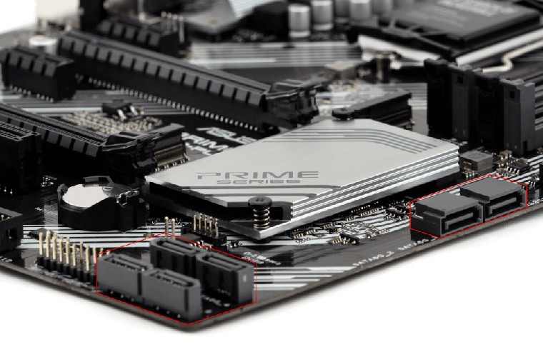
Pic. 1. SATA ports on the mainboard.
The unused SATA ports may be disabled in your system by default. If so, you will have to enable them manually in the BIOS settings.
The SATA power cable in this case should go to the SATA port on the system’s PSU. If their number is smaller than the number of SATA drives, a single socket can be split into two or more connectors via an additional SATA power splitter.
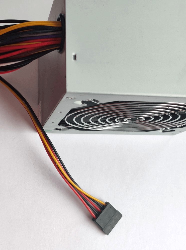
Pic. 2. SATA power port on the PSU.
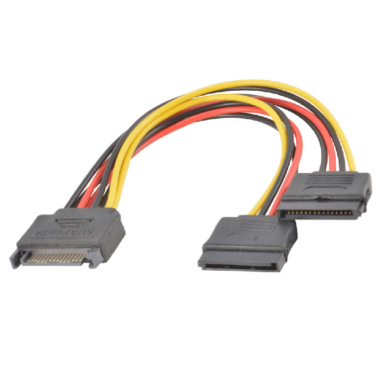
Pic. 3. SATA power splitter.
Hint: Please find an instruction that will help you to connect SATA drives directlyto the computer’s motherboard.
When it turns out that the motherboard lacks enough ports for connecting the required SATA drives, they can be attached via an expansion card. This device plugs into its PCIe slot and provides additional connectivity for specific types of devices via compatible cables. Also referred to as a Host Bus Adapter (HBA), such a card is distinguished by the type of interface it offers. In case of SATA, either a SATA or SAS HBA can be used, since the newer SAS standard is backwards compatible.
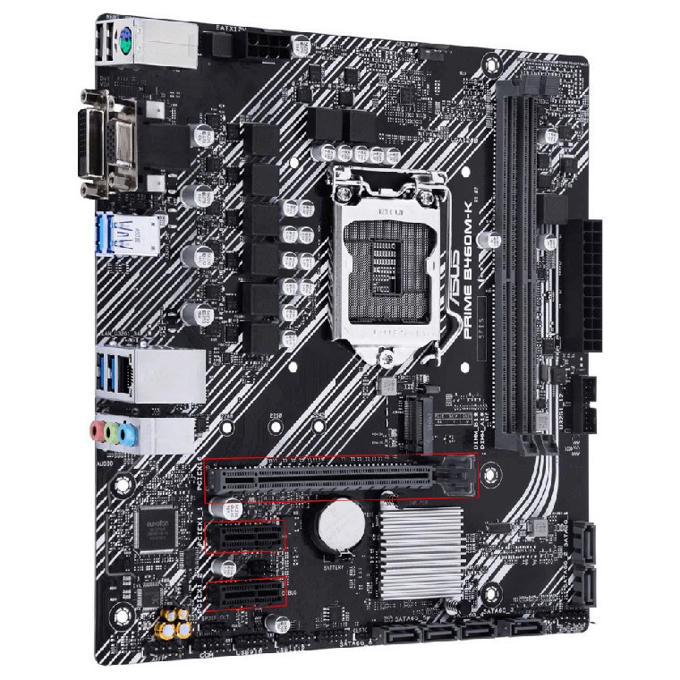
Pic. 4. PCIe ports on the mainboard.
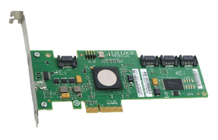
Pic. 5. SATA Host Bus Adapter.
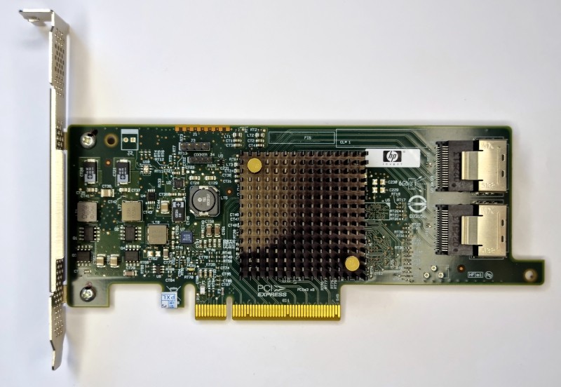
Pic. 6. SAS Host Bus Adapter.
It should be noted that PCIe slots come in different configurations, depending on the count of physical lanes: x1, x4, x8, x16 or x32. Hence, the card’s lane requirement must also be taken into consideration, as this factor defines its performance and determines whether it will be compatible with the available PCIe sockets.
Besides, older Host Bus Adapters may have restrictions on the capacity of the drives they can accommodate. The drives over 2 TB may not be supported and will show up as ones of 2 TB, whilst the rest of the capacity will simply get inaccessible.
Hint: Please refer to the manual on installation of SATA drives via an expansion card for detailed steps.
External methods for connecting SATA drives
The use of a SATA hard drive or SSD externally requires a special USB to SATA adapter that will establish its communication with the standard USB port found in most modern PCs and laptops.
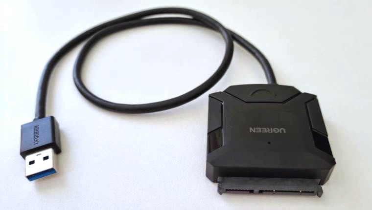
Pic. 7. USB to SATA adapter.
A USB port is capable of both transferring the data and powering the drive. However, it puts out a relatively small amount of current. This will suffice to run compact 2.5-inch HDDs as well as SSDs. But 3.5-inch hard drives use up more energy, that is why they require a separate power supply. An AC/DC power adapter may be already included into the kit. If not, the USB to SATA adapter should at least have a 12 V input port – then you can purchase the power adapter separately and employ it with more power-hungry spinning drives.
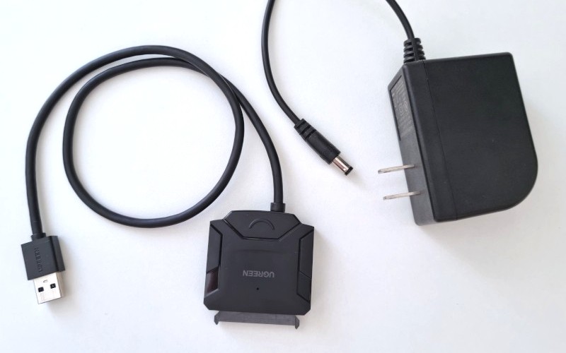
Pic. 8. SATA HDD powered via AC/DC adapter.
It is also noteworthy that not all of these USB to SATA converters are equal. High performance can be achieved only with the models featuring at least the USB 3.0 version of this bus, while older USB 2.0 devices will be considerably slower. In addition, most of them do not work with drives over 2 TB, and only some USB 3.0 and higher options may handle drives up to 6 TB.
Hint: The implementation of this method is demonstrated in the tutorial on connecting SATA drives with the help of a USB to SATA adapter.
The electronics of a USB to SATA adapter may be embedded into a special protective casing that encompasses the drive. These gadgets are known as external drive enclosures. They can be made of plastic or metal and are available in many designs.
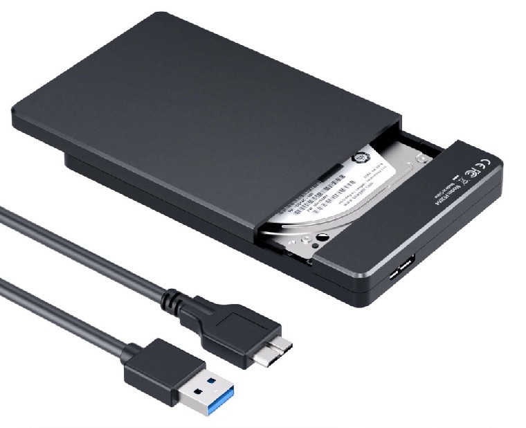
Pic. 9. External enclosure for SATA drives.
The size of an enclosure should be chosen in accordance with the drive’s form factor. Some enclosures can accommodate only 2.5-inch digital media, while others accept desktop-class 3.5-inch mechanical drives. It may also be possible to fit a 2.5-inch drive in a more capacious enclosure using a special cage or mounting bracket.
The majority of enclosures hold a single SATA drive, but high-end ones may be equipped with multiple bays for two or more drives.
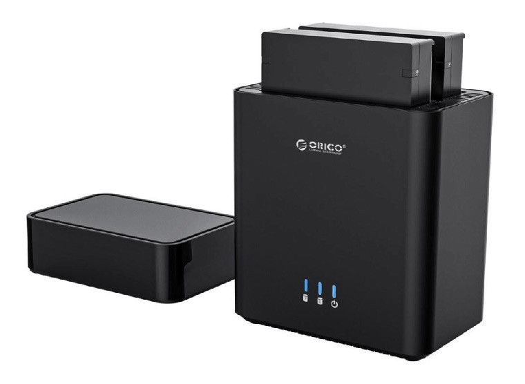
Pic. 10. External enclosure with multiple drive bays.
Though this method has inherited the limitations of a basic USB to SATA converter, it is more preferable for long-term connection in view of its greater security.
Hint: Please rely on the tutorial to learn how you can connect SATA drives with the help of an external enclosure.
Last update: November 15, 2022